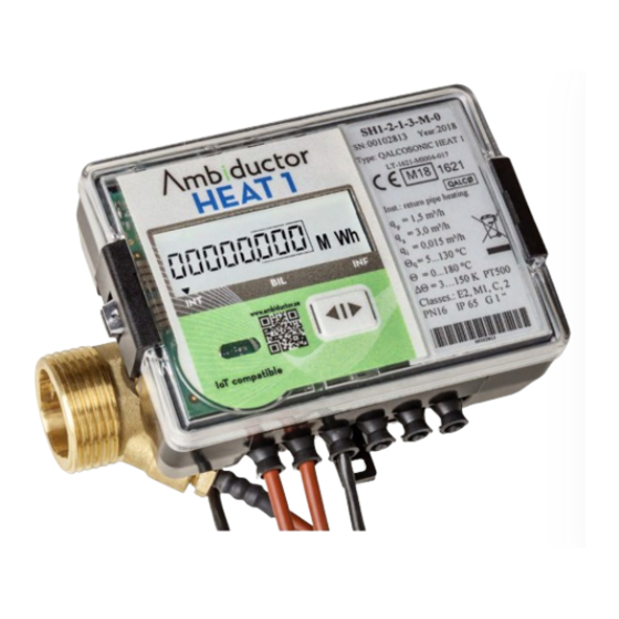
Ambiductor HEAT 1 Manuale di istruzioni per il funzionamento e il montaggio - Pagina 17
Sfoglia online o scarica il pdf Manuale di istruzioni per il funzionamento e il montaggio per Strumenti di misura Ambiductor HEAT 1. Ambiductor HEAT 1 20.

Power supply
Internal battery
2 type AA 3.6VDC 2.4 Ah Lithium battery (Li-SOCL2).
Designed to last at least 11 years.
24V module
12 ... 42 VDC or 12 ... 36 VAC 50 / 60Hz max 10mA + internal
battery backup (AA 3.6VDC 2.4 Ah Lithium battery (Li-SOCL2).
The power supply module replaces one battery.
230V unit (external)
230VAC (+ 10 / -30%) 50/60 Hz, approx. 10mA in.
12VAC 40mA (max) out.
Remote reading
Optical interface can be used for reading data from the meter.
The optical head is placed on the meter and connected to RS-
232 or USB.
In addition to remote reading via IR, it is also possible to use
two pulse outputs, or one of the following communication
modules.
Wired communication:
•
M-Bus (default)
•
Modbus RTU
•
BACnet TCP
•
LON
•
CL module (current loop)
Wireless communication:
•
Lora
•
wireless M-bus T1 OMS
•
wireless M-bus S1 (and Axioma bi-directional radio)
All modules have separate documentation. The modules can
also support mounting in other of our meters.
Our meters are normally backwards and forwards compatible
with old and new modules.
Optical interface
Integrated in the front panel of the calculator. It is used for
data reading via the M-bus protocol and parameterization of
the meter.
The optical interface is activated only after pressing the button
and automatically shuts off after 5 minutes after the last key
press or after the data transfer is completed via the interface.
M-bus
The cards use 1.5mA (1 M-bus load). See separate documen-
tation.
Ambiductor AB reserves the right to make changes without prior notice. Reprinting or copying this publication without permission is prosecuted.
Lora
Separate documentation is available. The meter can be con-
nected to any network server and application server. Param-
eter list can be obtained on request.
LoRa meters can be remotely programmed with MAC com-
mands. Contact Ambiductor for more information.
Pulse outputs
The pulse outputs are active when the jumpers of the connec-
tor (J) are open (see Setting the Jumpers J)
No communication interface affects measurement values and
their calculation, and can therefore be replaced by another
type without removing the seal.
Data collection from meters can be done via PC, modem, GSM,
broadband etc.
Number of possible
outputs
Pulse type
Pulse length
Pulse values (energy and volume) of pulse output device in
operating mode according to the table below:
Energy pulse output #1
Energy units
kWh, MWh
Pulse value, energy
Energy pulse output #2
Permanent flow
rate qp m3/h
Pulse value, flow
rate
Pulse inputs
The pulse inputs are active when the jumpers of the connector
(J) are closed (see Setting the Jumpers J)
Number of pulse inputs
Measuring units
Pulse value
Pulse type
Maximum frequency of
pulses
Max voltage on pulses
Bus communication limitation
The total working time for serial communication interfaces (to
protect the battery from premature discharge) is limited to
130 minutes per month. The remaining time for communica-
tion is stored in the calculator. The interface is blocked after
reaching the limit and only after the start of the next hour, the
new time limit on communication will be given (to 11 seconds
for each subsequent hour).
To release the restriction, connect external power supply and
follow the instructions at www.ambiductor.se/support.
This requires connection via m-bus or optical IR port.
17
2 pcs (OB normal mode, OD test mode)
Open collector (transistor), permitted cur-
rent up to 20 mA, voltage up to 50V
100 ms - in normal operating mode, 1.6
ms - in test mode
GJ
1 kWh/p
0,005 GJ/p
0,6...6,0
10...60
1 l/p
10 l/p
2
m3
Programmable
IB acc. LST EN1434-2
3 Hz
3,6 V
Gcal
0,001Gcal/p
