- ページ 7
インターホン・システム ASL INTERCOM PS 279のPDF ユーザーマニュアルをオンラインで閲覧またはダウンロードできます。ASL INTERCOM PS 279 16 ページ。 Dual channel master station
6.0
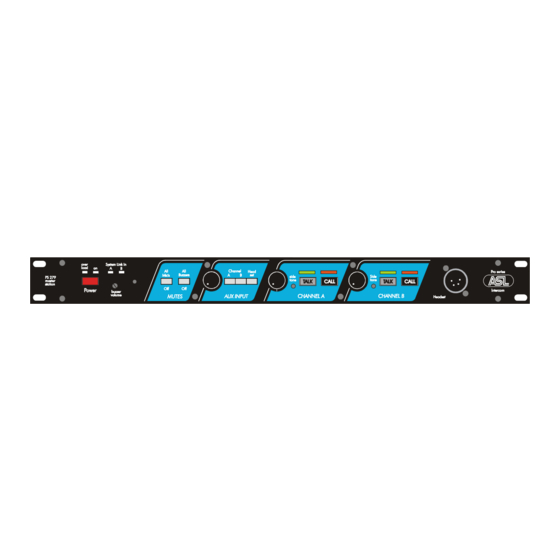
FRONT PANEL CONTROLS AND CONNECTOR
12
VOLUME control knobs
These knobs adjust the listen level of the headset.
Each channel can be adjusted separately.
13
SIDETONE trimmers
These trimmers adjust the level of your own voice as
you hear it in your headset.
Adjustment procedure:
set the trimmer in start position: fully clockwise.
-
switch off the microphone of all connected
-
(speaker!) stations.
switch on the microphone of the required channel.
-
-
turn up the volume of the required channel.
-
speak into the headset microphone.
adjust the listen level by turning the sidetone
-
trimmer.
The operating area is between fully clockwise and
minimum level. Adjusting the sidetone does not affect
the level of your voice as it is heard by other stations.
14
TALK buttons
These buttons allow you to talk to each channel
separately or simultaneously.
The large green LED is lit when the talk function is
activated.
Latched switching:
When a TALK button is pressed shortly, the
microphone of the chosen channel will be switched on
and latches electronically. When pressed again, the
microphone will switch off.
Momentary switching:
When holding a TALK button pressed while talking,
the microphone will remain switched on until the
button is released. Then the microphone will switch off
automatically.
User manual PS 279 / Issue 1 © 2006 ASL Intercom, Utrecht, The Netherlands
15 CALL A & B buttons
These push buttons activate the CALL system. A
momentary push will send a visual CALL signal to all
stations connected to that intercom channel and the
CALL LEDS will start flashing.
When holding the buttons pressed for 2 seconds, the
buzzer will be activated.
After the CALL button is released the LEDS will
continue to flash for further 2 seconds.
16 HEADSET connector
A XLR-4 type connector to connect the local headset.
The headset-can must have an impedance of 200
ohms or greater, or each 400 ohms minimum when in
parallel. The mic may be of the dynamic or electret
type.
Pin assignments:
1.
shield mic. (GND)
2.
mic. +
3.
phones +
4.
phones –
The wiring is such that both headset cans are connected
in parallel and receive the same signal. The two
headphone amplifiers run in a bridged mode.
As an option, an XLR-6 type connector can be fitted to
allow a binaural headset configuration where a different
signal will appear on each can. In this mode the internal
headphone amplifiers are not bridged.
See section 7.1 Internal Jumpers and Controls.
7