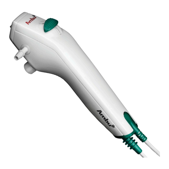
医療機器 Ambu aScope 3 RegularのPDF クイックマニュアルをオンラインで閲覧またはダウンロードできます。Ambu aScope 3 Regular 2 ページ。 Ascope 3 family

Ambu
aScope
®
- Quick Guide for intubation and single lung ventilation
1.
Functions
The aScope
3 Slim, aScope
TM
Large are the perfect choice for flexible fibreoptic intubation
as they are ready to use whenever you need them. The
single–use and ready–to–go concept simplifies flexible
fibreoptic intubation and improves patient safety.
aScope
3 Slim, aScope
3 Regular, and aScope
TM
TM
sterile and single-use flexible scopes with a 1.2 mm, 2.2 mm
or 2.8 mm working channel respectively.
For intubation the aScope
TM
size 5 and up, aScope
TM
3 Regular with ET tubes size 6 and up
and aScope
TM
3 Large with ET tubes size 7 and up.
For single lung ventilation aScope 3 Slim can be passed
through DLT's of FR 37 or greater or BB of sizes 5–9.
Warning: Read Instructions For Use before using the aScope
2.
Connecting the system
1. & 2. Connect aScope
TM
3 to the aView
plugging the aScope
TM
3 connector – white with
blue arrow - into the corresponding blue female
connector on the side of aView
3.
Preparation for use
•
Ensure that the selected ET tube
or DLT/BB is compatible with the
aScope
3 chosen.
TM
•
Lubricate the insertion cord with
a medical grade lubricant to
ensure the lowest possible friction.
Do not get lubrication or any other
contaminant on the tip of the
aScope
TM
3.
•
Attach the suction tube to the suction
connector and ensure that the
suction works when pressing the
suction button
•
Fluids can be instilled through the
working channel by inserting a
syringe into the working channel
port at the top of the aScope
When using a Luer Lock syringe,
use the included introducer.
3 Family
™
3 Regular and aScope
3
TM
TM
3 Large are
TM
3 Slim can be used with ET tubes
TM
by
3. Push the ON/OFF
button on the aView
to start up the system.
TM
.
•
If you are using a preformed ET
tube unbend it before inserting
the cord of the aScope
•
Antifogging agent is not required
with this device.
•
Confirm that the bending section
functions smoothly and correctly by
carefully sliding the bending control
lever forward and backward in each
direction.
•
Confirm that the bending section
returns to a straight position.
•
Connect the aScope
aView
and verify that a live video
TM
image appears on the screen.
•
Always have an additional aScope
TM
3.
at hand as a precaution.
3 and aView
TM
TM
4. The real time image
TM
will appear on aView
after only a few seconds
and the aScope
system is ready to use
3 through it.
TM
3 to the
TM
TM
3
TM
TM
3
Turn the page
