- ページ 7
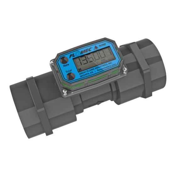
計測機器 Flomec TM10NのPDF 製品取扱説明書をオンラインで閲覧またはダウンロードできます。Flomec TM10N 13 ページ。 Electronic water flowmeters
INSTALLATION
IMPORTANT: TM Series meters are available with either a computer for
local electronic display, or three versions of output modules (see
section of this manual) to provide a digital signal to customer interfacing
equipment. TM Series meters with computer display ship pre-configured
from the factory in either gallons or liters. The volume unit can be changed
to several other options. Refer to the Q9 owner's manual for details on
changing or customizing the volume unit.
Connections
Install your meter in-line either horizontally or vertically. Installation to metal
connections is not recommended. Install as follows:
1. Plan to install turbine with a minimum straight pipe length as follows
(see Figure 2):
• Upstream from the turbine, allow a minimum straight pipe length of 10
• Downstream from the turbine, allow a minimum straight pipe length of
2. For Spigot (Pipe) End use only primer and solvents approved for PVC
gluing.
For NPT and BSP Fittings wrap all connections with 3 to 4 wraps of thread
tape (optional to use pipe thread sealant). Make sure the tape does not
intrude into the flow path.
3. Attach meter with arrow pointed in the direction of fluid flow.
4. For NPT and BSP Fittings - Hand tighten the meter at the housing ends.
Do not use a wrench or similar tool to tighten. This can damage the
housing.
UPSTREAM
10X I.D.
Figure 2
times the internal diameter of the turbine.
5 times the internal diameter of the turbine.
DOWNSTREAM
5X I.D.
Direction of Flow
PARTS
7