- ページ 10
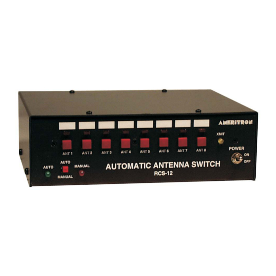
スイッチ AMERITRON RCS-12のPDF 取扱説明書をオンラインで閲覧またはダウンロードできます。AMERITRON RCS-12 16 ページ。 Automatic antenna switch

Ameritron RCS-12 Instruction Manual
Auxiliary Input
The Auxiliary Input Port allows remote control of the antenna buttons on the antenna switch. The port is a
female DB-9 connection with the pin-out shown below. Applying a ground to any of the Aux pins will
select the appropriate antenna. Each pin is a +5Vdc with a 10K ohm resistor series circuit. When pulled
low, it will deliver .5 ma.
Auxiliary Output
The Auxiliary Output Port has two functions depending on the setting of JMP3. The output can be either
band data in 1 of 8 format or the current antenna selection. The default setting is band data.
On the Band Data setting , the output is the transceiver's band in 1 of 8 format for HF. UHF/VHF bands
uses two pins. Pin 9 is also a TX line that goes to ground when the transmitter is keyed. This band data
can be used to control another device that can accept data in 1 of 8 format. The diagram below shows the
pin-out for each HF band.
Auxiliary Output
*Ground is on the shell of the DB-9 plug
Auxiliary Input Port
Band Data
Pin 1 – 160m
Pin 2 – 80m
Pin 3 – 40m
Pin 4 – 30m
Pin 5 – 20m
Pin 6 – 17m
Pin 7 – 15m
Pin 8 – 12m/10m
Pin 9 – TX Key
Auxiliary Input Pin-Out
Pin 1 – Antenna 1
Pin 2 – Antenna 2
Pin 3 – Antenna 3
Pin 4 – Antenna 4
Pin 5 – Antenna 5
Pin 6 – Antenna 6
Pin 7 – Antenna 7
Pin 8 – Antenna 8
Pin 9 - Ground
Antenna Out (1 of 8)
Auxiliary Output (Band Data Setting)
8
Automatic Antenna Switch
