- ページ 11
スイッチ AMERITRON RCS-12のPDF 取扱説明書をオンラインで閲覧またはダウンロードできます。AMERITRON RCS-12 16 ページ。 Automatic antenna switch

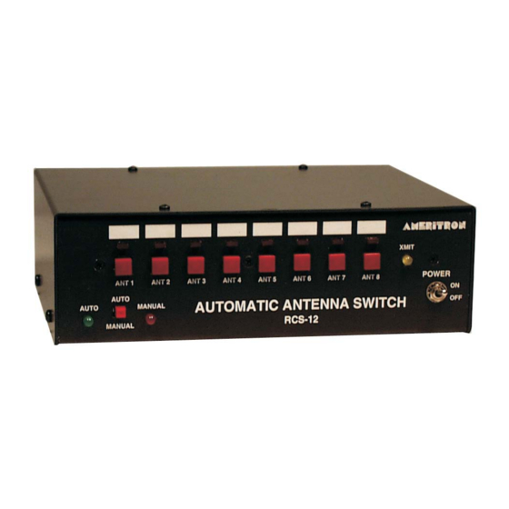
Ameritron RCS-12 Instruction Manual
When the transceiver or antenna is selected for a particular band. The pin on the Auxiliary Output jack
will corresponding to the band will be 5V. When using UHF/VHF the output from the Auxiliary Output
port will be as follows:
NOTE: Some radios output the same band data for two bands such as the Icom (15m& 17m,
12m & 10m). Even though the radio has changed bands, it may not be reflected in the
band data output of the radio.
When the Auxiliary Output Port has been configured for Antenna Out. The output will correspond to the
currently selected antenna. Pin 9 is a TX line that goes to ground when the transmitter is keyed. The
diagram below shows the pin-out of the jack. The currently selected antenna's pin on the Auxiliary Out
will be +5V while the remaining pins will be 0V.
Auxiliary Output
*Ground is on the shell of the DB-9 plug
Radio Key In
The Radio Key In jack, when pulled to ground, will prevent the RCS-12 from switching antennas. The
Radio Key In jack is +5V open collector and will deliver 1mA when pulled to ground. This jack should
be connected to the transceiver's relay control line that goes to ground on transmit. This line is normally
used for keying an amplifier.
The Radio Key In jack and Pin 7 of the Radio Input Port are the same connection. Use only one of the
two connections.
Amp Key Out
The Amp Key Out jack will go to ground when the Radio Key In line is pulled to ground. This jack is
used for keying an amplifier's T/R relay control line. This line can accept up to 25VDC at 1A.
The Amp Key Out jack and Pin 9 of the Aux Output Port is the same connection.
Band
Pins
6m
1 & 8
Sub 2m
1 & 7
2m
1 & 6
70cm
1 & 5
33cm
1 & 4
23cm
1 & 3
Auxiliary Output (Antenna Out 1 of 8)
Pin 1 – Antenna 1
Pin 2 – Antenna 2
Pin 3 – Antenna 3
Pin 4 – Antenna 4
Pin 5 – Antenna 5
Pin 6 – Antenna 6
Pin 7 – Antenna 7
Pin 8 – Antenna 8
Pin 9 – TX Key
9
Automatic Antenna Switch
