- ページ 7
ゲートオープナー DoorHan PCB-SHのPDF プログラミング説明書をオンラインで閲覧またはダウンロードできます。DoorHan PCB-SH 12 ページ。 Control board
DoorHan PCB-SH にも: プログラミング説明書 (14 ページ), プログラミング説明書 (16 ページ)
1. ELECTRICAL CONNECTIONS
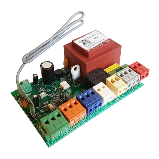
1.1. CONTROL UNIT SCHEMATIC DIAGRAM
WARNING!
Cable wires shall be protected against contact with any rough and sharp parts. All connections must be performed only
when the power is off.
Fig. 1. Control unit wiring diagram
WARNING!
If no safety devices are connected to PHCL and STOP terminals, then jumper COM terminal and PHCL and STOP con-
tacts.
LED
Function
Program
Operation mode is selected
SW OP
Limit switch to Open
SW CL
Limit switch to Close
OP
Open command
CL
Close command
PH CL
Photocells to Close
STOP
STOP command
Remote
Record of Remote controller code
*Bold type indicates LEDs status when the door is stopped in mid-position.
ELECTRIACAL CONNECTIONS
On
Flashes according to the selected mode of operation*
Does not respond
Does not respond
On
On
Do not respond
Off
On
Table 1. Control unit LEDs
Off
Responds
Responds
Off
Off
Respond
On
Off
7