DoorHan PCB-SH 프로그래밍 지침 매뉴얼 - 페이지 7
{카테고리_이름} DoorHan PCB-SH에 대한 프로그래밍 지침 매뉴얼을 온라인으로 검색하거나 PDF를 다운로드하세요. DoorHan PCB-SH 12 페이지. Control board
DoorHan PCB-SH에 대해서도 마찬가지입니다: 프로그래밍 지침 매뉴얼 (14 페이지), 프로그래밍 지침 매뉴얼 (16 페이지)

1. ELECTRICAL CONNECTIONS
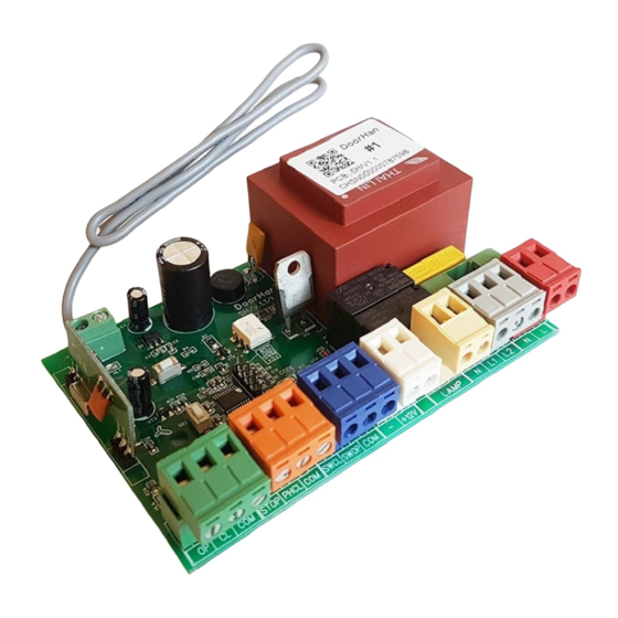
1.1. CONTROL UNIT SCHEMATIC DIAGRAM
WARNING!
Cable wires shall be protected against contact with any rough and sharp parts. All connections must be performed only
when the power is off.
Fig. 1. Control unit wiring diagram
WARNING!
If no safety devices are connected to PHCL and STOP terminals, then jumper COM terminal and PHCL and STOP con-
tacts.
LED
Function
Program
Operation mode is selected
SW OP
Limit switch to Open
SW CL
Limit switch to Close
OP
Open command
CL
Close command
PH CL
Photocells to Close
STOP
STOP command
Remote
Record of Remote controller code
*Bold type indicates LEDs status when the door is stopped in mid-position.
ELECTRIACAL CONNECTIONS
On
Flashes according to the selected mode of operation*
Does not respond
Does not respond
On
On
Do not respond
Off
On
Table 1. Control unit LEDs
Off
Responds
Responds
Off
Off
Respond
On
Off
7
