- ページ 4
コントロールユニット Doug Fleenor Design Preset12のPDF オーナーズマニュアルをオンラインで閲覧またはダウンロードできます。Doug Fleenor Design Preset12 11 ページ。

INSTALLATION
WIRING
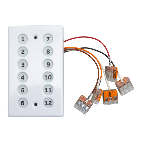
Signal and power are connected to Preset12's flying leads. Five Wago Lever Nuts are provided
for this purpose. The supplied 3-position nuts are rated for 12 to 22 gauge wires. Wires are to be
stripped to 7/16" (11mm) before insertion into the nut, with the lever up. Closing the lever
secures the wire connection. The three nut positions are intended to connect: 1)The Preset12
lead, 2)Signal/power "IN", 3)Signal/power "THROUGH". Preset12's color codes are:
Black:
White:
Brown:
Red:
Orange:
Wiring Notes:
Color codes for DMX512 follow the resistor color code: 1=Brown, 2=Red, 3=Orange.
If multiple Preset12 are wired to the same AC supply, all Preset12's Black wires must be
connected together as must all White wires.
The Brown wire (DMX512 common) and the Black wire (Power supply "Negative") are
connected internally.
POWER SUPPLY
Preset12 has been designed to operate on a standard 10 Volt class 2 "doorbell" transformer, or
7 to 18 Volts regulated DC. Power is applied to the White and Black leads; if DC, positive to
White and negative to Black. Although polarity does not matter with AC, if multiple Preset12s are
supplied by the same transformer winding, the Black wires of all Preset12s must be connected
to the same transformer terminal.
MOUNTING
Two 6-32 x 7/8" oval head mounting screws are provided. Alternate #6 hardware may be used.
Preset12's mounting holes are on 3.281" (3
gang electrical boxes or rings. When surface mounting (no back-box) a ½" diameter through-
hole is required, centered between the mounting holes, for Preset12's flying leads.
Power supply (Negative if DC power)
Power supply (Positive if DC power)
DMX512 common (pin 1 of an XLR connector)
DMX512 Data- (pin 2 of an XLR connector)
DMX512 Data+ (pin 3 of an XLR connector)
") centers for mounting to North American single
9
/
32
Page 4 of 11
