- ページ 2
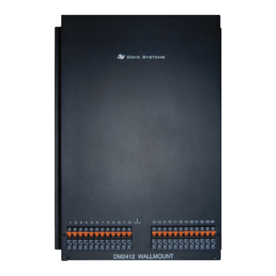
調光器 Dove DM-2412のPDF オーナーズマニュアルをオンラインで閲覧またはダウンロードできます。Dove DM-2412 6 ページ。 Digital dimmer

OWNER'S MANUAL
:Table of Contents
// SETUP AND CONNECTION\\
A Mechanical Installation\\
B Electrical Installation\\
C Grounding\\
D Load Connections\\
E Control Connections\\
F Channel Selection and Testing\\
G Indicators\\
H Internal Switches\\
// Control Connections
// TROUBLESHOOTING CHART\\
// WARRANTY INFORMATION\\
DOVE LIGHTING SYSTEMS
04-07
04
04
05
05
05-06
07
07
07
08
09-10
11
805.541.8292\\805.541.8293
INC.\\3563 SUELDO STREET UNIT E
SAN LUIS OBISPO\\ CA 93401
OWNER'S MANUAL
:SETUP AND CONNECTION
A// Mechanical Installation
Remove all packing material from the unit. Make certain that all holes
are free of obstruction on all sides of the unit. Replace all packing
material in the carton and store it for reuse. The backplane mounting
holes are spaced 16" on center for convenient wall mounting. Do not
block any vent holes. Make certain that the vent holes all have at
least 6 inches of free air around them. It is essential that this unit
have adequate cooling for safe, reliable performance. Maximum air
temperature must not exceed 40 degrees Centigrade (105 degrees
Fahrenheit).
B// Electrical Installation
The dimmer must be supplied with an amount of current equal to the
combined total current of the lamps it controls. To calculate this
current, use the formula amps = watts ÷ volts. For example, if
twenty-four 1200-watt, 120 volt lighting units are connected to the
dimmer, it would require 28,800÷120, or 240 amps total power when
all channels are at full. This is available from a three phase 4 wire
80 amp or a single phase 3 wire 120 amp service. Usually this much
power is not required and a 40 - 60 amp service may be used with lower
power loads plugged in.
The Dimmermaster accepts either three phase or single phase power
input and is factory configured for three phase. Line to neutral
voltage is always 120 volts. Line 1 to Line 2 voltage is 208 volts in
three phase service and 240 volts in single phase service. It is very
important that the input voltages be checked with a meter to insure
that they are correct. A mistake can place 208 to 240 volts across
a 120 volt lamp. The breakers will protect the unit but may not save
the lamps. A double check of voltages before applying power can guard
against such disaster. The power input connector is a terminal block.
Each leg of the power feed connects to one terminal on the dimmer
pack. These are marked "L1", "L2", and "L3". The neutral connection is
made on the neutral bar, just to the right of the power block. The
ground connection is made on the ground terminal, just below the
power block. The pack has circuit breakers to protect each dimmer
channel, but the primary circuit protection and disconnect is to be
provided by the user. When single phase service is used switch S2,
located near the center of the plug-in circuit board, must be moved
from the 3 phase position to the 1 phase position. The power input
terminal marked "L3" is not used. The two blue wires wrapped with red
tape must be moved to the terminalmarked "L1" and the two wrapped
with black tape to "L2". The tiny blue wire stays in terminal "L3".
DOVE LIGHTING SYSTEMS
805.541.8292\\805.541.8293
INC.\\3563 SUELDO STREET UNIT E
SAN LUIS OBISPO\\ CA 93401
