- ページ 3
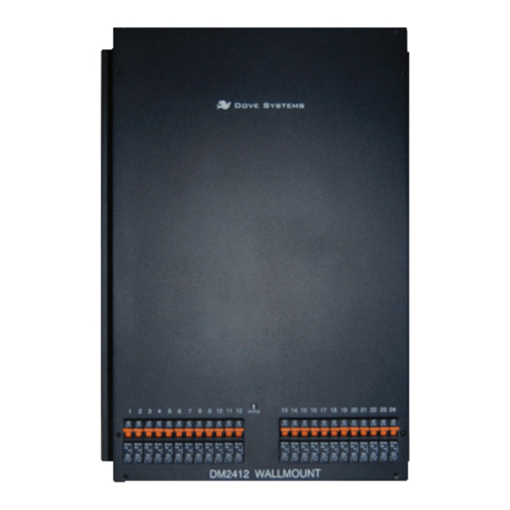
調光器 Dove DM-2412のPDF オーナーズマニュアルをオンラインで閲覧またはダウンロードできます。Dove DM-2412 6 ページ。 Digital dimmer

OWNER'S MANUAL
C// Grounding
The term GROUNDING refers to a separate wire with green insulation
which is connected from the equipment case to earth ground
(often through a properly grounded conduit system). This is not the
same as the neutral or common and must not be confused with them.
The neutral is a separate, load-carrying circuit conductor. The ground
conductor should not normally carry current. When the
Dimmermaster is connected to its power source by conduit, the ground
connection can be made via the conduit itself. If flexible conduit is
used, a separate bonding conductor will usually be required.
Always check your local codes for hook-up before operating this
equipment. It is recommended that power connections to the
Dimmermaster be made by a qualified electrician.
D// Load Connections
The dimmer pack consists of 12 or 24 dimming channels.
The Dimmermaster will dim any load from 1 watt through 1200 watts
or 1 watt through 2400 watts at 120 volts for a 2412 and a 1224
respectively. The load may be incandescent, inductive, or resistive.
This includes conventional incandescent, quartz incandescent,
rain-lights, pin beams, and similar lamp loads. This does not include
fluorescent or neon lamps. Fluorescent lamps with dimmable ballasts
may be dimmed by other means; consult the factory for help.
There is one lug for each output and a neutral bar for all neutrals.
Lugs are numbered according to their circuits. There should be a
separate neutral returning from each load circuit.
E// Control Connections
The Dimmermaster 1224 and 2412 can take either of two control
protocols: USITT DMX-512 or 0 to +10VDC analog. All control
connections are made on connectors or terminals inside the pack.
Positions are labeled as to function. The optional power supply
sends power to passive controllers (those that do not plug into
the wall).
DOVE LIGHTING SYSTEMS
805.541.8292\\805.541.8293
INC.\\3563 SUELDO STREET UNIT E
SAN LUIS OBISPO\\ CA 93401
OWNER'S MANUAL
:Control Connections
DMX Connector DB25M Analog
1
Common 1 Channel 1 Control (0 to 10V)
2
- Data 2 Channel 2 Control (0 to 10V)
3
+ Data 3 Channel 3 Control (0 to 10V)
4
Return Data opt 4 Channel 4 Control (0 to 10V)
5
Return Data opt 5 Channel 5 Control (0 to 10V)
6
Channel 6 Control (0 to 10V)
7
Channel 7 Control (0 to 10V)
8
Channel 8 Control (0 to 10V)
9
Channel 9 Control (0 to 10V)
10
Channel 10 Control (0 to 10V)
11
Channel 11 Control (0 to 10V)
12
Channel 12 Control (0 to 10V)
13
Channel 13 Control (0 to 10V)
14
Channel 14 Control (0 to 10V)
15
Channel 15 Control (0 to 10V)
16
Channel 16 Control (0 to 10V)
17
Channel 17 Control (0 to 10V)
18
Channel 18 Control (0 to 10V)
19
Channel 19 Control (0 to 10V)
20
Channel 20 Control (0 to 10V)
21
Channel 21 Control (0 to 10V)
22
Channel 22 Control (0 to 10V)
23
Channel 23 Control (0 to 10V)
24
Channel 24 Control (0 to 10V)
25
Common
When the temperature of the heatsink exceeds 75 degrees Celsius,
the control is cut off. This prevents overheating. When the heatsink
cools, the loads begin to work again. If this happens, the air
circulation around the dimmer should be improved. Check that the
internal fan has not failed.
DOVE LIGHTING SYSTEMS
805.541.8292\\805.541.8293
INC.\\3563 SUELDO STREET UNIT E
SAN LUIS OBISPO\\ CA 93401
