- ページ 5
ガレージドアオープナー Cardale safeliftのPDF 取付説明書をオンラインで閲覧またはダウンロードできます。Cardale safelift 6 ページ。 Trackless door gear
www.thegaragedoorcentre.co.uk
To other
side latch
Latch lever
FIG 8
9
CAUTION Do not close door from
outside until all latches have been
checked for correct setting and
operation. Failure to follow these
instructions carefully may result in a
lock out situation and a chargeable
service call may result.
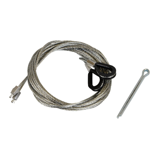
Take cable with double loop and attach
looped end of cable (without clamp) in
centre groove of nylon latch (see fig. 8).
Loop the other end of the cable over the
closest arm on the internal latch lever.
Repeat this operation for both side latches.
Remove 'Park pins' to release latches (see fig.
8). The setting mark on the nylon latch (see
fig. 8) indicates nominal latch position but
adjustment may be necessary to ensure
correct latch engagement. This can be done
by either looping the cable over a different
groove in the latch (see fig. 8) or by
loosening the screw on the cable clamp,
moving cable slightly and re-tightening.
IMPORTANT Test latches for correct
operation.
•
Side latches should engage behind side
i
On completion of installation lubricate the spring, wheel spindles and all pivot points
with a '3 in 1' type lubricant.
ii
Grease top catch pin to ensure smooth operation. (Do not grease side latches).
iii
Check that all fasteners are fully tightened.
iv Ensure track runners are clean and door operates smoothly through full open/close cycle.
v
It is the responsibility of the installer to ensure that the spring tension is correctly set.
If the tension requires adjustment, refer to maintenance label on rear of door.
vi Do not paint spring or any moving parts.
www.thegaragedoorcentre.co.uk
Nylon latch
Park pin
Setting
mark
Cable clamp
and screw
NOTES ON COMPLETION
0800 525 442
Outside
Black plastic
weather strip
FIG 9
runners by approx. 6mm.
•
All latches should be fully released when the
external lock handle is rotated clockwise.
10
Fix black plastic weather strips (LH & RH) to
the side timbers using No.8 × 1" screws
provided (see fig 9). Position the weather
strip so that the shaped end fits around the
wheel spindle, between the security block and
edge flange of the runner. Any excess length
can be cut off from the bottom.
11
IMPORTANT Fix 19mm × 19mm
3
3
(
/
" ×
4
securely to the underside of the head
on the outside of the door (see fig.10).
Weather
beading
19 × 19
FIG 10
0800 525 442
www.thegaragedoorcentre.co.uk
Side timber
DOOR
18 REF
/
") wooden weather beading
4
Head Timber
Inside garage
www.thegaragedoorcentre.co.uk
"
No. 8 × 1
self tapping
screws