- ページ 11
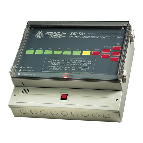
制御システム Formula Sound SENTRY MK2のPDF ユーザーマニュアルをオンラインで閲覧またはダウンロードできます。Formula Sound SENTRY MK2 17 ページ。 Environmental noise control system
Formula Sound SENTRY MK2 にも: ユーザーマニュアル (11 ページ)
Security Loop
Provision to connect a security loop is provided. This may be required for fire doors/alarm or
emergency cut off etc. Magnetically operated reed switches of the type used in intruder alarms are
most convenient for this application on doors or a simple emergency switch. If this facility is not
required a wire link must be connected to allow the Sentry to work normally. (see Drg No 879). A
front panel indicator shows if the security loop is opened.
Tampering
If you find that you have problems with unauthorised persons security screws are available to
replace the cover retaining screws, a special key is also supplied for the fitting and removal of
these screws. Contact FORMULA SOUND sales office for more details.
Internal Settings
Several optional settings are available internally. These are shown on drawing Drg No 879.
Internal/External Microphone Selection and Phantom power
This is accomplished by the position of three jumper plugs on pin headers. Take care to move
jumpers and ensure that they connect correctly. The positions are shown on drawing Drg No 879.
Weighting Selection
The position of jumper plugs select the response on the measuring microphone. The positions are
shown on the P.C.B. Ensure that the jumpers are seated correctly.
Special weighting options are possible - contact Formula Sound for further details.
External Microphone connection
A 3 way terminal strip is provided for the connection of a remote microphone. The microphone
should be low impedance, balanced and good quality twin screened cable should be used for the
connections. Contact Formula Sound if you are unsure.
Led Indicators
Outputs are provided for remote led indicators: - MIC TAMPER, LEVEL 2, WARNING, RESET
REQUIRED. If more than two leds are to be connected they share a common terminal. Led current
limiting resistors are not required. Leds may be connected directly. These outputs are also sufficient
to drive a contactor with low voltage interface if required.
Timer Adjustment
The period of time that noise "over limit" is tolerated before the unit trips out is variable over the range
of 10 - 70 seconds. If adjustment is required locate the timer pre-set from Drg No 879 and adjust with
a small terminal screwdriver as required. You may have to wait up to 70 seconds for the timing
capacitor to discharge before new timer settings will take place.
11