- ページ 12
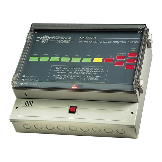
制御システム Formula Sound SENTRY MK2のPDF ユーザーマニュアルをオンラインで閲覧またはダウンロードできます。Formula Sound SENTRY MK2 17 ページ。 Environmental noise control system
Formula Sound SENTRY MK2 にも: ユーザーマニュアル (11 ページ)
Fire alarm interface
The fire alarm interface jumpers setting the mode of operation are located beneath the display panel.
To access first switch off power to the unit, open the perspex display cover and remove the screws
from the display panel. Drop the display panel forward a couple of inches and reach in to release the
ribbon cable connector attaching the display assembly to the main unit.
The fire alarm interface connector and settings are located top right corner, on the PCB there is a
legend "FIRE ALRM".
To set the mode of operation first set the jumpers for voltage sensing or contacts sensing ("VOLTS
SENSE" and "CONT SENSE"). If the fire alarm is applying or removing a voltage then set for "VOLTS
SENSE", if the fire alarm is closing or opening contacts set for "CONT SENSE".
If voltage sensing is selected next set voltage applied or voltage removed ("V.A" or "V.R.").
If contact sensing is selected set for contacts normally closed or contacts normally open (located by
legend "CONTACTS" and "N.C." or "N.O.").
Replace the display, the ribbon cable connector is keyed so ensure it goes it the correct way round (if
you feel any resistance when pressing home the connector it may be in the wrong way round).
Switch the Sentry on and reset it, perform a fire alarm test to ensure the Sentry trips when the fire
alarm operates.
Remote Reset
A remote reset facility can be added by connecting a momentary action push button or key switch.
Site this in a Manager's office or behind the bar or other suitable location.
Formula Sound offer both remote push button (074P) and remote keyswitch (074K) options in a grey
plastic lighting style surface mount box. Connection of either 074P or 074K is as follows:
Open the remote reset box and the connections are on the back of the front panel as shown below.
LED COMMON -VE
RESET REQUIRED
LED +VE
RESET
SWITCH
The box contains LED's that show if the Sentry is tripped (reset required) or if the sound level is near
the limit (warning).
Behind the panel below the main display is a grey connector strip (see drwg 879 later in manual).
To connect LED's and switch a 5 core wire is required (low voltage dc and low current), a 6 core
microphone cable would be suitable.
Connect the "RESET SWITCH" terminals to the Sentry terminals marked "N" (Remote reset switch)
on drwg 879.
WARNING LED +VE
12