- ページ 5
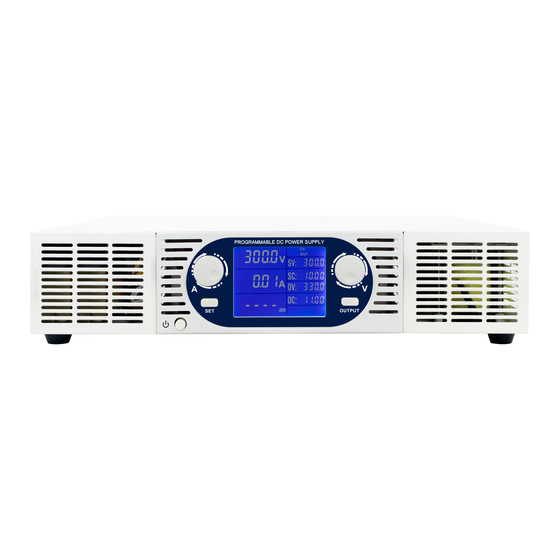
電源 DSC ELECTRONICS DP-D SeriesのPDF ユーザーマニュアルをオンラインで閲覧またはダウンロードできます。DSC ELECTRONICS DP-D Series 14 ページ。 High power laboratory power supplies

DP-D Series User's Manual
Version 08.01.2019
3.3 Inductive load
Note: Can be ignored for devices with optional inductive reverse current protection.
If the power supply is used with large inductive loads, voltage spikes with an amplitude of up to 5 times the output
voltage can occur, this may damage the power supply or lead to unstable operation. To protect the power supply from
damage, a freewheeling diode has to be used in parallel with the load.
3.4 Switches
If a mechanic switch is used to connect or disconnect the power supply from the load, electric discharge can occur
during switching on currents over 100A. This may cause unstable output. To prevent this behaviour, connect a RC
circuit to the switch contact point.
4. Front Panel Description
No.
Name
1
Voltage
2
Current
3
C.C indicator
4
C.V indicator
5
Output indicator
6
OV indicator
7
OL indicator
8
OT indicator
9
Current setting
10
Voltage setting
11
Preset key
12
Output ON/OFF
13
Power switch
14
PR indicator
15
FI Indicator
Description
Displays the output voltage
Displays the output current
Constant Current mode indicator
Constant Voltage mode indicator
Output status indicator
Over Voltage protection ON
Overload protection ON
Over temperature protection ON
Adjusts the current setting
Adjusts the voltage setting
Press this button to set voltage and current preset
Use this key to turn on or off the output
Use this switch to turn on or off the power supply
PRESET Mode ON (Digital devices only)
Voltage / Current fine tune mode (Digital devices only)
DSC-Electronics Germany • Georgstraße 36 • 53111 Bonn
DSC-Electronics Germany • Georgstraße 36 • 53111 Bonn
