- ページ 7
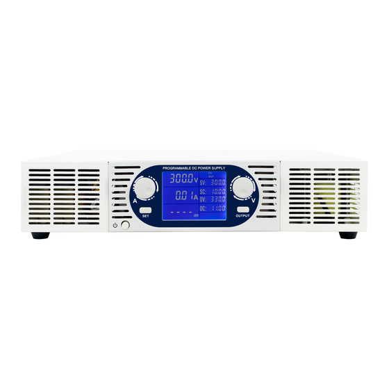
電源 DSC ELECTRONICS DP-D SeriesのPDF ユーザーマニュアルをオンラインで閲覧またはダウンロードできます。DSC ELECTRONICS DP-D Series 14 ページ。 High power laboratory power supplies

DP-D Series User's Manual
Version 08.01.2019
5.4 Constant Current Operation
1. Turn on the power and check that the output is off.
2. Press / hold PRESET and set the desired current and voltage.
4. Turn the output on by pressing the OUTPUT button.
5. The CC indicator lights up as soon as the output current reaches the current limit set.
The power supply now operates in constant current mode (CC). The output current remains stable while the voltage is
being adjusted automatically.
5.5 Optional: Constant Power Operation
1. Turn on the power and check that the output is off.
2. Press / Hold PRESET and set the desired maximum voltage, current and power.
4. Now turn the output on by pressing the OUTPUT button.
The device now regulates the output voltage as a function of the load in order to remain at the maximum limit (current
/ power) reached as the first.
5.6 Optional: Remote Sensing
The power supply is optionally equipped with remote sensing terminals, which can read the voltage at the load and
therefore compensate losses. Refer to below figure on how to connect the load to remote sensing terminals. The
remote sensing input can be connected optionally, and is automatically deactivated if not connected.
5.7 Optional: Timer
Power supplies of the DP-D series can be equipped with an integrated timer to control the output status. The
Panasonic Timer Model LT4HW-AC240VS can be set to two time periods, T1 and T2. The operation sequence is
started with the toggle switch "START" or stopped "STOP".
Working modes of the timer
Pu-A:
When the toggle switch is set to "START", the timer starts counting down at T1 (output OFF) until the time set for T1
has expired and then changes to the second state T2 (output ON). This state is retained until the time set for T2
elapses, the output then returns to the original state (output Off) and ends the process.
Pu-B:
When the toggle switch is set to "START", the timer starts counting down at T1 (output OFF) until the time set for T1
has expired and then changes to the second state T2 (output ON). This condition is retained until the time set for T2
elapses, the output then returns to the original state T1 (output Off) and starts the procedure from the beginning.
Pu-C:
When the toggle switch is set to "START", the timer starts counting down at T1 (output On) until the time set for T1
has expired and then changes to the second state T2 (output Off). This state is retained until the time set for T2
elapses, the output then returns to the original state T1 (output On) and starts the process from the beginning.
Switching the working modes
DSC-Electronics Germany • Georgstraße 36 • 53111 Bonn
DSC-Electronics Germany • Georgstraße 36 • 53111 Bonn
