- ページ 12
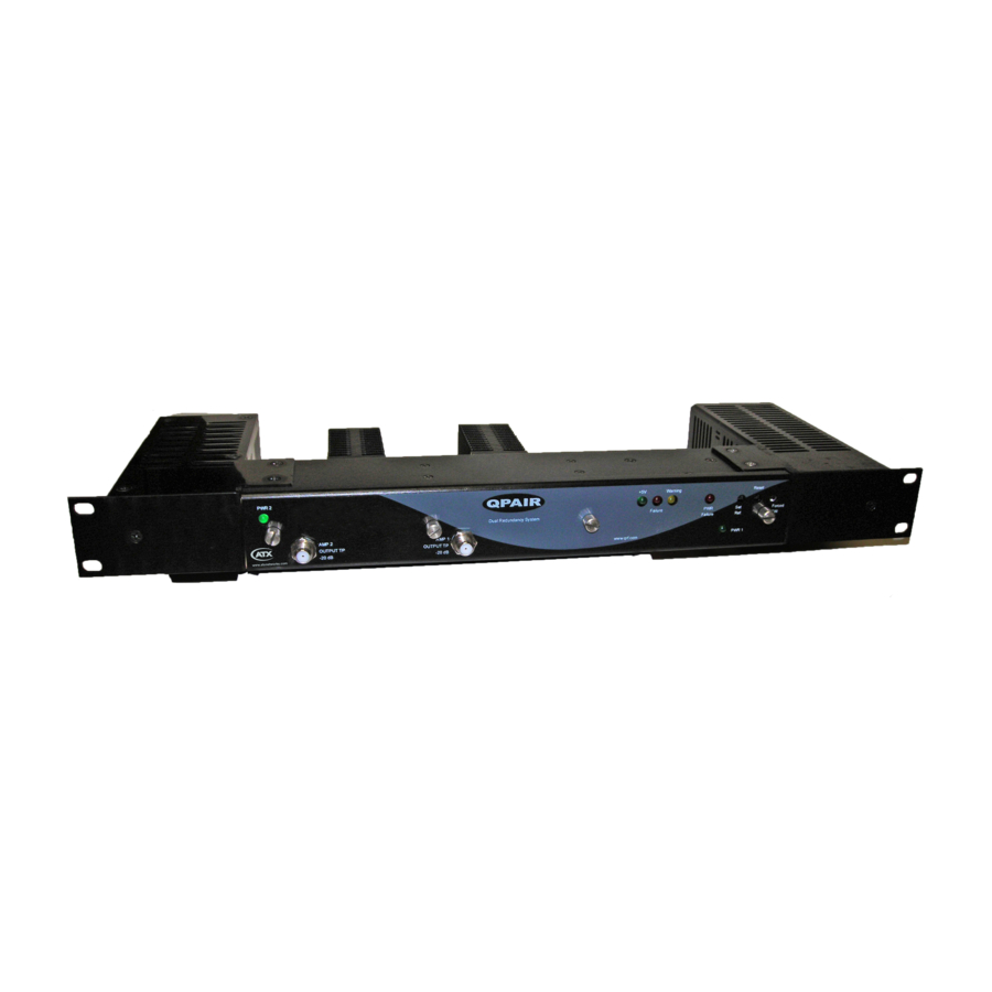
アンプ ATX Q seriesのPDF インストレーション&オペレーションマニュアルをオンラインで閲覧またはダウンロードできます。ATX Q series 18 ページ。 Qpair redundancy switch amplifier system

CHAPTER 3: SET-UP PROCEDURE
APPENDIX
APPENDIX 1: Method of Removing the Front Cover
The front cover is held in place by captive thumbscrews. A partially threaded hollow tube guides the screws on the back of
the cover. When removing, the screws need to be turned counterclockwise until they feel loose from the fastener located in
the bottom of the amplifier/switch sections. Then CONTINUE to turn the screw counterclockwise a few more turns to hold it
in place in the threaded hollow tube. This keeps the screws from moving loosely around and possibly shorting out the circuits
when re-installing the lid. The lid may now be removed by pulling on the two outer screws simultaneously. When re-installing
the lid, just reverse the procedure for removing the lid. After the lid is in the proper position to re-install, then the screws can
be turned clockwise into the fastener. This procedure will prevent damage to the amplifier or switch.
APPENDIX 2: Procedure for Removing/Replacing a Modular Amplifier (refer to Figure 2)
First, unplug the red power wire from the module you are removing. This power wire is located at the upper edge of the
module and is plugged onto the board by a socket. Pull straight up away from the board and the power wire will come loose
from the connection. Next, remove all equalizers and pads to make it easier to work with the thumbscrews. Loosen the 2
knurled thumbscrews with slotted screwdriver by turning counterclockwise until the screw is free of the threaded heat sink.
Continue turning the thumbscrews to until the screw is held stable by the threads on the standoff of the circuit board. These
screws are located in the center of the board. Do not remove the Phillips screws that hold the hybrid module in place. Only
loosen the 2 knurled thumbscrews in the horizontal centerline of the board. Now, you should be able to pull up on the screws
to free the board from the push-on connectors. You will then need to tilt the board as you remove it so as to clear the power
feed-thru connections. DO NOT TRY TO OPERATE THE MODULE OUT OF THE CHASSIS BECAUSE IT REQUIRES THE
SINK TO DISSIPATE THE HEAT. To replace the board, just reverse the procedure. However, be sure to use a small amount
of heat sink compound on the amplifier plate where it mates up to the heat sink.
Figure #2 - QPAIR RF Amplifier Module
APPENDIX 3: Amplifier Troubleshooting Suggestions
To troubleshoot RF level problems with either amplifier, it is best to have normal input signal levels to the amplifier module.
For example, if the secondary amplifier (AMP 2) is in service, then the primary amplifier is switched with no RF input/output.
A quick method to check amplifier level issues is to disconnect the RF IN and RF OUT cables from AMP 1 on the back of
the chassis (in this scenario). You could now use another signal source from some other part of the headend to put standard
signal levels into the RF IN port. Now use a signal level instrument to measure the output level on RF OUT. If the amplifier
gain is lower than the gain in the specification sheet, you will need to remove the amplifier module and contact QRF for a
repair/replacement module. DO NOT TRY TO OPERATE THE MODULE OUT OF THE CHASSIS BECAUSE IT REQUIRES
THE SINK TO DISSIPATE THE HEAT. If the primary amplifier (AMP 1) is in service, the secondary amplifier is switched
so that the input level is 25 dB lower than normal. You may disconnect the RF IN cable and the RF OUT cable from AMP
3-2
Q-Series
Amplifiers – QPAIR Redundant Amplifier System – Installation & Operation Manual
®
