- ページ 13
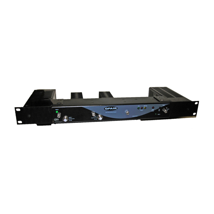
アンプ ATX Q seriesのPDF インストレーション&オペレーションマニュアルをオンラインで閲覧またはダウンロードできます。ATX Q series 18 ページ。 Qpair redundancy switch amplifier system

CHAPTER 3: SET-UP PROCEDURE
2 (secondary amplifier) on the back of the chassis and complete the troubleshooting methods as described above for
AMP 1.
APPENDIX 4: Removal/Replacement of Power Supply (See next page for Figures 3 & 4)
If you need to remove and replace either of the power supplies, you will need to remove 5 screws and unplug 2 wires
connecting the power supply to the chassis. Two screws are located on the top and 2 screws are located on the bottom
and one screw is located on the front of the power supply. The screws on the top and bottom are located on the tab of
the power supply enclosure where it fastens to the chassis. The front screw goes through the front plate of the QPAIR.
Just remove these 5 screws and then hold the power supply as you locate the 2 wires connecting to the chassis. Just
unplug the wires from their sockets and the power supply removal is complete. To replace a power supply, just reverse
the above procedure. Observe the positive and negative polarity of the wires and feed-thru "studs" when you plug the
sockets onto the "studs".
Figures 3, 4, & 5 will assist in removing/replacing power supply.
Figure #3 - Screws on Tabs Securing Power Supply
Figure #4 - One Screw on Front Securing Power Supply
Q-Series
Amplifiers – QPAIR Redundant Amplifier System – Installation & Operation Manual
3-3
®
