- ページ 3
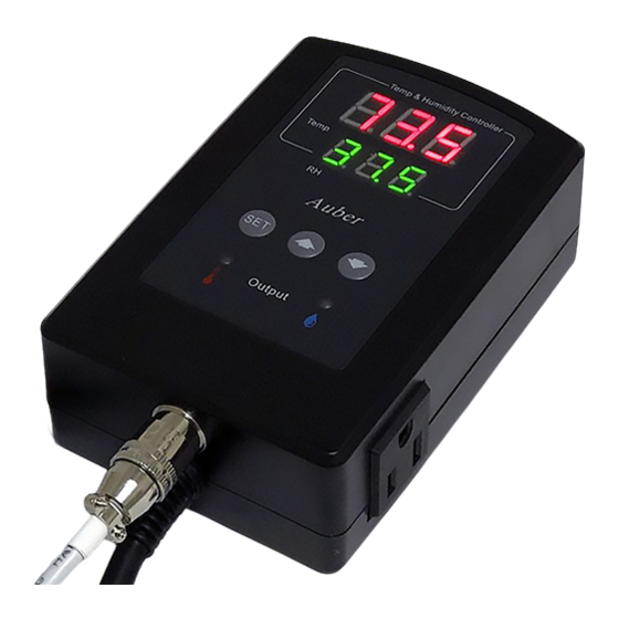
温度コントローラー Auber Instruments TH220のPDF 取扱説明書をオンラインで閲覧またはダウンロードできます。Auber Instruments TH220 3 ページ。 Temperature and humidity controller

AUBER INSTRUMENTS
gets back to the alarm zone again, the alarm will be on again. To resume the
alarm, press the Up key, the alarm indicator will be off.
To disable the alarm, set High Limit Alarm = Low Limit Alarm.
Note 4. When The controller is used for cooling (or dehumidifying control) and
load is a compressor, it should not turn on the compressor when it is at high
pressure (just after turned off). Otherwise, it may shorten the life of
compressor. The Anti-Short Cycle Delay function can be used to prevent the
rapid cycling of the compressor. It establishes the minimum time that the output
contact remains open (after reaching cutout) before closing again. The delay
overrides any load demand and does not allow the output contact to close until
the set time-delay value has elapsed. It gives time to release the refrigerant
pressure through evaporator. It is typically set to 4-6 (minutes).
Note 5. The TSF (HSF) can be set to ON or OFF. When it is set to ON, the
output will always be on when the sensor fails; when it is set to OFF, the output
will always be off when the sensor fails.
For example, when the unit controls a refrigerator for food, you may want to set
the TSF to ON if the sensor fails to keep the food cold. When it controls a
heater, you may want to set the TSF to OFF for safety purpose.
Note 6. Menu selection parameter. tE menu is for temperature control settings;
Hu menu is for humidity control settings and SYS is for system settings. SYS
setting is only available to TH220-W model.
Note 7. Device access password (only available to TH220-W model). This
parameter is used to lock the access to parameter settings on AuberSmart
app. Please refer to figure 3.
6. How to install the sensor to the unit.
The connector of sensor contains a slot for fitting pin connection. It locates at
the bottom of the controller. It also has a spring lock to prevent disconnections
from accidental pulling on the cable.
To install the sensor to the controller: 1) Identify the key on the male sensor
connector (Figure 4, a) and the notch on the female connector (Figure 4, b). 2)
Hold the tail of the female connector, align the notch and the key, and push the
female connector forward.
To remove the connector, hold the spring-loaded collar on the female
connector and pull it back. Please see Figure 5.
2017.10
E-mail: [email protected] Tel: 770-569-8420
Copyright 2007-2017, Auber Instruments All Rights Reserved.
No part of this manual shall be copied, reproduced, or transmitted in any way
without the prior, written consent of Auber Instruments. Auber Instruments
retains the exclusive rights to all information included in this document.
(a)
WWW.AUBERINS.COM
Figure 4. Install the sensor.
Figure 5. Remove the sensor.
Auber Instruments
5755 North Point Parkway, Suite 99
Alpharetta, GA 30022, USA
www.auberins.com
(b)
(c)
P3/3
