- ページ 2
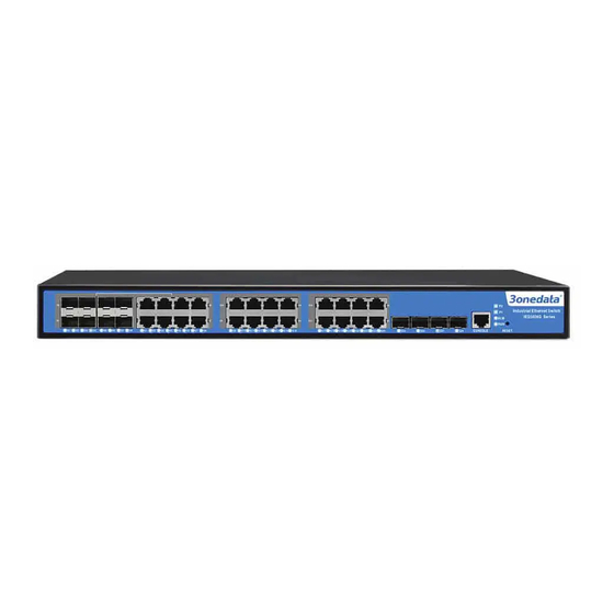
ネットワーク・ルーター 3onedata ICS5028G SeriesのPDF ユーザーマニュアルをオンラインで閲覧またはダウンロードできます。3onedata ICS5028G Series 5 ページ。 Layer 3 industrial

Rear panel
1. Restore factory settings
2. Console port
3. Systems running LED
4. The power LEDs (P1, P2)
5. Relay alarm LED
6. 10/100/1000BaseT(X) (RJ45) ports
7. Ethernet port Link/ACT LEDs(1~28)
8. 1000Base-FX SFP port
9. Rackmount ears
10. Relay 1 output terminal block
11. Power 1 input power socket
12. Grounding screw
13. Relay 2 output terminal block
14. Power 2 input power socket
15. 10/100/1000BaseT(X) or 1000Base SFP slot combo ports
ICS5028G-4TS-2P (100~240VAC)
Front panel
ICS5028G-4TS -8GC-2P (100~240VAC)
Front panel
Rear panel
1. Restore factory settings
2. Console port
3. Systems running LED
4. The power LEDs (P1, P2)
5. Relay alarm LED
6. 10/100/1000BaseT(X) (RJ45) ports
7. Ethernet port Link/ACT LEDs(1~28)
8. 10 Gigabit Ethernet SFP+ slot
9. Rackmount ears
10. Relay 1 output terminal block
11. Power 1 input power socket
12. Grounding screw
13. Relay 2 output terminal block
14. Power 2 input power socket
15. 10/100/1000BaseT(X) or 1000Base SFP slot combo ports
【Power supply input】
The switch support dual redundant power supplies: Power Supply
1 (P1) and Power Supply 2 (P2). The switch rear panel provides
power sockets for AC100~240V power entered. Socket diagram is
as follows:
The redundant power can be used independently. P1 and P2 can
supply power at the same time, once either of these two powers
fails, another power can acts as backup automatically to ensure
reliability of the network.
Important notice:
1. Power ON operation: Please connect to the device at first and
then connect to the power supply with power cable.
- 2 -
2. Power switch "—" means power ON, "O" means power OFF.
3. Power OFF operation: First, the powers switch to the "O" side
and then disconnect the power supply. Finally disconnect the
connection between the device and the power cord.
【Dimension】
The series of products are the same size, and the number of the
Ethernet interface is different. Unit (mm)
【Relay connection】
Relay access terminals in the rear panel of the device, next to the
