- ページ 5
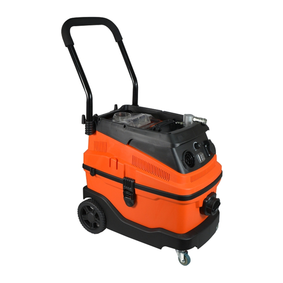
掃除機 4CR 9500のPDF マニュアルをオンラインで閲覧またはダウンロードできます。4CR 9500 8 ページ。 Industrial vacuum cleaner

INDUSTRIAL VACUUM CLEANER EN
- Do not vacuum sanding dust from surfaces treated with paints that have not completed the catalyst cycle;
- Do not vacuum sparks or white hot shavings;
- Immediately disconnect the vacuum from the electrical mains if dust is ejected from air outlet;
- Do not vacuum flammable or explosive liquids (i.e. petrol, thinners, etc.);
- Do not vacuum aggressive liquids or substances (i.e. acids, bases, solvents, etc.).
SPECIFIC USE
- This appliance is suitable for heavy duty and industrial operations in accordante with EN60335-1 e EN60335-2-69;
- This appliance is suitable for commercial use: i.e. hotels, school, hospitals, factories, shops, offices and rental business;
- The front power socket is only intended for specific use as indicated in the present instruction manual.
START-UP
ASSEMBLY
- Mounting of the dust extraction hose (2)
Insert the hose fitting into the hole located on the top of the vacuum cleaner and turn it clockwise until it locks.
To detach the hose, hold the hose and turn the hose fitting counter-clockwise and remove it.
- Mounting of the extension to the dust extraction hose (3)
Attach the extension to the hose connector and lock it by turning it clockwise. To detach the extension, hold the extension by
one hand and detach the hose connection by turning it counter-clockwise with the other hand.
- Mounting of the floor brush (4)
Attach the brush hose to the extension and lock it by turning it clockwise. To detach the floor brush, hold the extension by one
hand and detach the floor brush hose by turning it counter-clockwise with the other hand.
- Installation of the front wheels (5)
Remove the upper part of the vacuum cleaner body. Insert the steering axles of the two front wheels as far as they will go into
the corresponding holes located on the lower part of the vacuum cleaner body.
- Storing of the power cord (6)
When the vacuum cleaner is not in use, store the cord on a special holder located on the back of the vacuum cleaner.
- Storing of accessories (7)
Store accessories in special holes located on the both sides of the top part of the vacuum cleaner.
- Blow function (8)
Insert the hose fitting into the hole located on the front part of the vacuum cleaner.
- Improvement of suction power (9)
If the suction power has decreased press the button using the hose fitting for 3-5 times to increase the suction power.
POWER SUPPLY
- Turn the main switch (Pos. 7, Picture 1) to "0" (Off) before connecting this appliance to the supply mains;
- Supply mains voltage and frequency must match the identification plate;
- Connect to power socket outlets provided with earth conductor and adequate protections.
COMPRESSED AIR MAINS
- Do not exceed 6 bar;
- Dehumidified and filtered air required;
- Connect the appliance to the compressed air main with an hose suitable for the air pressure and int. diam. 10 mm min.
ELECTRICAL TOOL CONNECTIONS
- Check for the tool switch turned off before connecting it to the front panel socket outlet;
- Insert the tool plug into the front panel socket (Pos. 16, Picture 1) and (18);
- Connect the tool to the hose nozzle with the hose (Pos 18, Picture 1);
- Do not plug electric tools exceeding the power indicated on the front panel.
PNEUMATIC TOOL CONNECTIONS
5
