- ページ 4
コントロールユニット GAC ESD-5550 SeriesのPDF マニュアルをオンラインで閲覧またはダウンロードできます。GAC ESD-5550 Series 8 ページ。 Speed control unit
GAC ESD-5550 Series にも: 技術情報 (12 ページ), マニュアル (8 ページ)
4
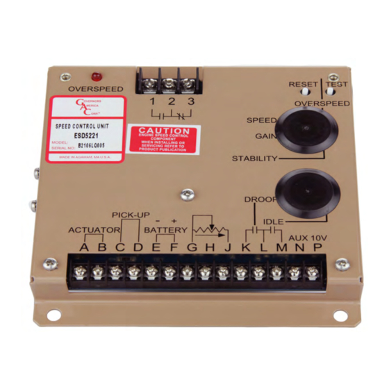
WIRINg (CONTINUED)
TermInaL
DefInITIon
A & B
ACTuATOR (+/-)
PICK-uP *
C & D
(D is ground)
E & F
BATTERy (-/+)
G
GROuND
H & G
Droop Range
J
Variable Speed Input
K & L
DROOP Select
M
Idle Select
N
Accessory Input
P
Accessory Power Supply
*
Magnetic speed sensor wires connected to Terminals C and D MuST BE TWISTED AND/OR SHIELDED for their entire length. The speed sensor cable
shield should ideally be connected as shown. The shield should be insulated to insure no other part of the shield comes in contact with engine ground,
otherwise stray speed signals may be introduced into the speed control unit. With the engine stopped, adjust the gap between the magnetic speed sensor
and the ring gear teeth. The gap should not be any smaller than 0.020 in. (0.45 mm). usually, backing out the speed sensor 1/4 to 1/2 turn after touching
the ring gear teeth will achieve a satisfactory air gap. The magnetic speed sensor voltage should be at least 1.0 V AC RMS during cranking.
acceSSorY InPUT
Auxiliary Terminal N accepts input signals from load sharing units, auto synchronizers, and other governor system accessories.
GAC accessories are directly connected to this terminal. Terminal N connections must be shielded.
If the auto synchronizer is used alone, not in conjunction with a load sharing module, a 3 Ω resister should be connected between
noTe
Terminals N and P. This is required to match the voltage levels between the speed control unit and the synchronizer.
acceSSorY SUPPLY
Terminal P supplies +10 volt regulated supply to provide power to GAC governor system accessories. up to 20 mA of current can be drawn
from this supply. Ground reference is Terminal G.
A short circuit on Terminal P can damage the speed control unit.
aDDInG a PoTenTIomeTer
use a single remote speed adjustment potentiometer to
adjust engine speed. Select the desired speed range and the
corresponding potentiometer value.
If the exact range is not found select the next higher range
potentiometer. Connect the potentiometer as shown in the
WIRING diagram.
use #16 (1.3 mm
) or larger wire. Long cables require an increased wire size to minimize
2
voltage drops.
•
Wires must be twisted and/or shielded for their entire length
•
Gap between speed sensor and gear teeth should not be smaller than 0.02 in. [.5mm]
•
Speed sensor voltage should be at least 1 V AC RMS during crank
•
#16 (1.3 mm
) or larger wire
2
•
A 15 amp fuse must be installed in the positive battery lead to protect against reverse
voltage
•
Battery positive (+) input is Terminal F must be fused for 15 amps as shown in the Wir-
ing diagram in this section to protect against reverse voltage.
Add jumper to decrease droop range
0 - 5 V DC
Droop active when closed
Close for Idle
Load Sharing / Synchronizing,
Supplies +10 V regulated supply to accessories. No more than 20 mA of current can be
drawn from this supply. Ground reference is Terminal G. A short circuit in this terminal can
damage the speed control unit.
SPeeD ranGe
900 Hz
2,400 Hz
3,000 Hz
3,500 Hz
3,700 Hz
4
noTeS
PoTenTIomeTer
1K
5K
10K
25K
50K
ESD5550-5570 Series Speed Control Unit 9-2020-E PIB1003
Governors America Corp. © 2020 Copyright All Rights Reserved