- ページ 6
コントロールユニット GAC ESD-5550 SeriesのPDF マニュアルをオンラインで閲覧またはダウンロードできます。GAC ESD-5550 Series 8 ページ。 Speed control unit
GAC ESD-5550 Series にも: 技術情報 (12 ページ), マニュアル (8 ページ)
5
ADJUSTMENTS (CONTINUED)
aDJUSTInG STaBILITY
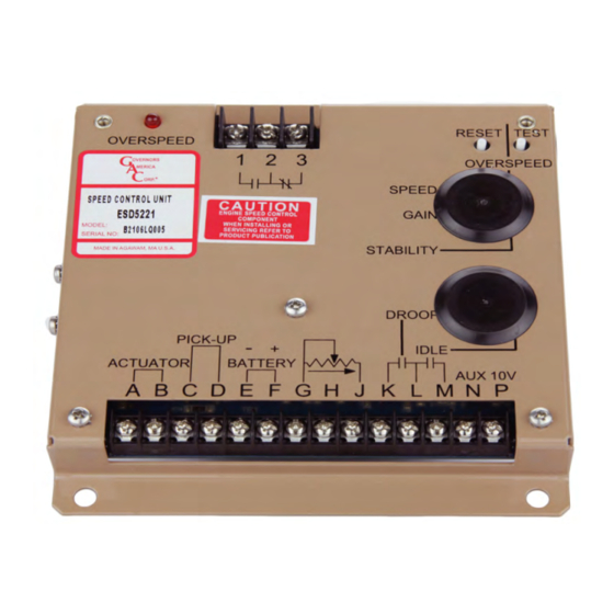
The governed speed set point is increased by a CW rotation of the SPEED adjustment control (25 turn pot.). Remote speed adjustment
can be obtained with an optional 5K Speed Trim Control. See section 4, Wiring diagram.
Once the engine is at operating speed and at no load, the following governor performance adjustment can be made.
ParameTer
1.
Rotate the GAIN adjustment clockwise until instability develops.
GAIN
2.
Gradually move the adjustment counterclockwise until stability returns.
3.
Move the adjustment one division further counterclockwise to ensure stable performance (270° potentiometer).
4.
If instability persists, adjust the next parameter.
1.
Rotate the STABILITy adjustment clockwise until instability develops.
STABILITy
2.
Gradually move the adjustment counterclockwise until stability returns.
3.
Move the adjustment one division further counterclockwise to ensure stable performance (270° potentiometer).
Normally, adjustments made at no load achieve satisfactory performance. If further performance improvements are required,
noTe
refer to section 7, SySTEM TROuBLESHOOTING.
LeaD cIrcUIT anD SofT coUPLInG
The engine's exhaust smoke at start-up can be minimized by completing the following adjustments:
1.
Switch 1 (SW1) controls the Lead Circuit. The normal position is ON. Move the switch to the OFF
position if there is fast instability in the system.
2.
Switch 2 (SW2) controls a circuit designed to eliminate fast erratic governor behavior, caused by very
soft or worn couplings in the drive train between the engine and generator. The normal position is
OFF.
3.
Move to the ON position if fast erratic engine behavior due to a soft coupling is experienced
DrooP oPeraTIon
Droop is typically used for the paralleling engine driven generators. When in droop operation, the engine speed will decrease as engine
load increases. The percentage of droop is based on the actuator current change from no engine load to full load.
1.
Place the optional external selector switch in the DROOP position. DROOP is increased by clockwise rotation of the DROOP adjust-
ment control.
2.
After the droop level has been adjusted, the rated engine speed setting may need to be reset. Check the engines speed and adjust
that speed setting accordingly.
Though a wide range of droop is available with the internal control, droop level requirements of 10% are unusual. If droop levels experi-
enced are higher or lower than those required, contact GAC for assistance.
WIDe ranGe remoTe varIaBLe SPeeD oPeraTIon
Remote variable speed can be obtained with the an external potentiometer. A single remote speed adjustment potentiometer can be used
to adjust the engine speed continuously over a specific speed range.
1.
Select the desired speed range and corresponding potentiometer value as detailed in section 4, ADDING A POTENTIOMETER. If the
exact range cannot be found, select the next higher range potentiometer.
2.
Connect the speed range potentiometer as shown in WIRING Diagram.
3.
An additional fixed resistor may be placed across the potentiometer to obtain the exact desired range.
4.
To maintain engine stability at the minimum speed setting, a small amount of droop can be added by turning DROOP adjustment CW.
5.
At the maximum speed setting the governor performance will be near isochronous, regardless of the droop adjustment setting.
ProceDUre
6
ESD5550-5570 Series Speed Control Unit 9-2020-E PIB1003
Governors America Corp. © 2020 Copyright All Rights Reserved