- ページ 7
ツール Gage Bilt GB585AのPDF オリジナル取扱説明書をオンラインで閲覧またはダウンロードできます。Gage Bilt GB585A 20 ページ。 Installation tool
Gage Bilt GB585A にも: インストール (11 ページ)
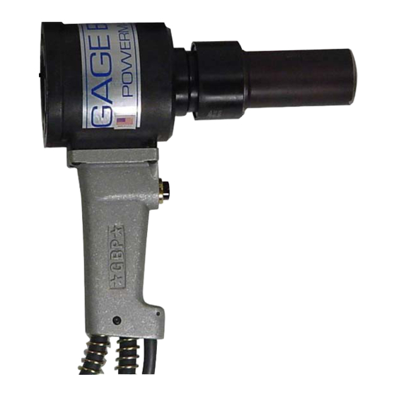
When the tool is connected to a powerunit, operation is controlled by an electric actuator switch (GB585) or a piloted air actuator
assy (GB585A) in the handle assy (480127). When the switch/actuator assy is depressed, a directional valve in the powerunit directs
oil to the front side of the piston (585124) forcing it and the nose assembly collet rearward. This action causes the jaws to clamp onto
the fastener pintail and pull the sheets together. The anvil is forced forward, swaging the collar into locking grooves of the fastener.
Further force breaks the pintail off, approximately flush with the collar.
When the switch/actuator assy is released the directional valve reverses oil flow to the back of the piston assy and pushes the nose as-
sembly off of the swaged fastener. The pintail ejector hydraulically pushes the spent pintail out of the nose assembly.
PULL Cycle
Pintail
Piston Travel
Ejector
Actuator
PULL Pressure
GB585 / GB585A INTALLATION TOOL
PRINCIPLE OF OPERATION
HYDRAULIC DIAGRAM
Relief
Valve
RETURN Pressure
Images may not reflect actual tool
Pintail
Ejector
Actuator
Pressurized Oil
Return Oil
7
RETURN Cycle
Piston Travel
RETURN Pressure
PULL Pressure
Relief
Valve
REV. 12/17