- ページ 3
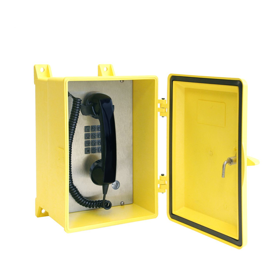
電話 GAI-Tronics 354-001 seriesのPDF ユーザーマニュアルをオンラインで閲覧またはダウンロードできます。GAI-Tronics 354-001 series 12 ページ。 Nema 4x industrial telephone
Pub. 42004-489D
Model 354-001 Series NEMA 4X Industrial Telephone
Page 3 of 10
Installation
WARNING
This product can contain hazardous voltages. Always remove power to this
station and any associated equipment before beginning any installation.
CAUTION
Do not install this equipment in areas other than those indicated on the
approval listing in the "Specifications" section of this manual. Such installation may cause a safety
hazard and consequent injury or property damage.
Install equipment without modification and according to all applicable local and national electrical codes.
Consult the National Electrical Code (NFPA 70), Canadian Standards Association (CSA 22.1), and local
codes for specific requirements regarding your installation. Class 2 circuit wiring must be performed in
accordance with NEC 725.55.
Security Hardware
The Model 354-001 series Telephone is vandal-resistant, with the front panel attached to its enclosure
with security screws. A GAI-Tronics Model 233-001 Security Screwdriver (sold separately) or Torx T-
25 security head tip (included with the telephone) is recommended for installing the security screws.
Conduit Installation Details
GAI-Tronics recommends installing telephone cable in conduit to protect against damage and vandalism.
Mounting and wiring of the Model 354-001 series Telephones must be in accordance with installation
standard practices.
Entering the enclosure from the top is not recommended. Bottom (preferred) or side entry helps prevent
condensation moisture from dripping onto the telephone electronics causing severe damage. If using
conduit, an appropriate hub (Myers STG series recommended) or a UL Listed NEMA 4X rated connector
appropriate for the installation should be used. If a top entry must be made, a drip path is strongly
recommended. Seal all conduit entrances around the entry point and inside the conduit using a silicone-
type sealant.
The Model 354-001 series Telephones are not supplied with openings for conduit or cable because of
potential installation variations. Conduit entrances must be installed prior to mounting the enclosure to
the wall surface.
1. Open the door and remove the front panel assembly (carefully set aside).
2. Drill (hole saw) or punch entry openings using the template provided with the telephone. There must
be a minimum of 1 inch (26 mm) of material between entry holes.
3. Install hub or fitting.
f:\standard ioms - current release\42004 instr. manuals\42004-489d.doc
01/15