- ページ 8
アンプ GAI-Tronics PA250-001のPDF マニュアルをオンラインで閲覧またはダウンロードできます。GAI-Tronics PA250-001 13 ページ。 250 watt central amplifier
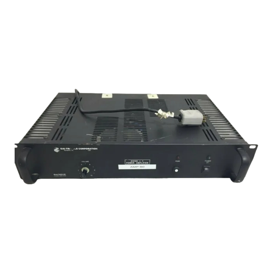
Model PA250-001 250 Watt Central Amplifier
600-ohm (balanced) and Tel-Page (balanced) Input
The 600-ohm balanced input and the Tel-Page balanced input (600-ohm) connections are made via screw
terminals on the rear audio input terminal block. Observe +/- polarity for proper signal phasing. Refer to
the Specification section for input sensitivity levels associated with the various inputs.
600-ohm/Tel-Page Audio Input Gain Control
This rear-mounted, recessed control allows adjustment of the 600-ohm/Tel-Page input level without
affecting the level of the Hi-Z inputs. This control works in conjunction with the master VOLUME
control located on the front panel. Both adjustments will have an effect on the output signal level from
these two input signals.
Dual Hi-Z inputs
The two H
-Z
(10-Kohm) are RCA-type female connectors that are paralleled internally. One
I
INPUTS
connection is for signal input, the other is for strapping to a second amplifier's input, if desired.
AUTO-MUTE for the Hi-Z Inputs
Audio signal applied to 600-ohm or Tel-Page input terminals will mute the two high impedance paralleled
inputs, unless defeated by the user. This mute feature is defeated by moving an internal jumper located
on the input PCBA, which is mounted on the back panel adjacent to the audio input terminal block
connections.
WARNING
Performing this AUTO-MUTE defeat modification requires the opening of the unit. This action should
be performed by qualified personnel only. Failure to follow instructions could result in damage to
equipment and/or injury to personnel.
Perform the following steps to move this jumper: Refer to Figure 2.
1. Unplug the ac power cord.
2. Remove the top cover assembly and locate the Input PCBA.
3. Find the header marked M
position.
4. Replace the top cover.
5. Reapply ac power.
Speaker Output Connections
The amplifier offers three different output connections to meet most system connection requirements.
Refer to Figure 4.
Direct 8-Ohm
Connect an 8-ohm speaker of proper power handling capability to the terminals marked 8-OHM
(BRIDGED). If adding more than one speaker, the resultant speaker line impedance should equal 8
ohms. Observe +/- polarity for proper signal phasing.
Note: This output is a BRIDGED output. DO NOT ground either of these terminals.
f:\standard ioms - current release\42004 instr. manuals\42004-340e.doc
06/02
. Move shorting plug from A (enable){factory default} to B (defeat)
UTE
Pub. 42004-340E
Page: 8 of 12