- ページ 2
コントローラー AutomationDirect CLICK C0-04TRS-10のPDF マニュアルをオンラインで閲覧またはダウンロードできます。AutomationDirect CLICK C0-04TRS-10 3 ページ。 Expansion i/o module

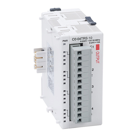
C0-04TRS-10 CLICK Expansion I/O Module
Installation and Mounting
1. Safety Installation, Wiring or Handling
• Discharge static electricity before installation or wiring in order to avoid
electric equipment damage.
2. Preface
• CLICK C0-04TRS-10 is supported by CLICK Programming software
Ver 2.60 or higher.
3. Compliant Crimp-type terminal
• I/O terminals
4. The following crimping ferrules are recommended for 24VDC terminal and
I/O terminals of CPU and Expansion I/O.
Company
Series
Zoller+Fröhlich
Twin Ferrules
* Rated torque is 0.5 N·m. Take care not to contact adjacent terminal.
5. Safety Standard
• To comply with safety standards, please observe and use the following.
Please use SELV (as defined by UL61010-2-201) and Limited Energy
(as defined by UL61010-1, 9.4)
Please ensure basic isolation is provided between each relay block.
In order to comply with IEC/UL 61010-2-201 if the output is connected
to a circuit lower than 30V, please provide an external isolation before
the relay output terminals. Basic isolation requires an air separation
of at least 1.5 mm, a creepage distance of at least 2.5 mm, and a
withstand voltage of 1500V rms.
Installing Expansion I/O Modules:
• Remove protective cover over bus port.
• Push the LOCK slide (top and bottom of modules) to "UNLOCK".
• Align module pins and tabs (attachment of modules) into adjacent
slots and firmly push together.
• Push the LOCK slides to "LOCK" to lock modules rigidly together.
Modules easily connect to each other.
3
2
1
OPEN
To remove an I/O module, first disconnect all phases of external
power source and wait
5 seconds
expansion I/O module of a functioning system.
Then push LOCK slides to "UNLOCK" and gently separate modules.
Copyright© 2020, Automationdirect.com Incorporated/All Rights Reserved Worldwide
www.automationdirect.com/click-plc
Model No.
Compliant Wire
* 0.5 mm
2
V30AE001134
(20AWG)
Locking Slides (Top and Bottom)
CLOSED
before installing or removing the
Additional Help and Support
• For additional technical support or questions, call our Technical
Support team @ 1-800-633-0405 or 770-844-4200
Safety Installation
Please heed the following instructions when
installing:
• Mount the CLICK PLC unit horizontally to provide
proper ventilation.
• Do not mount the CLICK PLC unit upside down, on
a horizontal surface, or in a vertical arrangement.
• There is a minimum clearance requirement of
2in. (51mm) from all sides of the cabinet and the
equipment.
• There is a minimum clearance requirement of 3in.
(76mm) from the wiring ducts and the equipment
• Please use this product in a metal enclosure/cabinet.
Air
Flow
Enclosures
It is important to select the appropriate enclosure to ensure safe and proper
operation of your CLICK PLC system. Control applications vary and yours may
require additional considerations. At a minimum your enclosure should include:
• Conformance to electrical standards
• Protection from the elements in an industrial environment
• Common ground reference
• Maintenance of specified ambient temperature
• Access to equipment
• Security or restricted access
• Sufficient space for proper installation and maintenance of equipment
• When installing modules and CPU on DIN rails, always
use end brackets on both ends of assembly.
• You should use 35mm width DIN Rails.
• You should use M4 size screws when you surface mount.
• You should tighten the screws with a spring washer and
a small round washer and torque (0.5 to 0.6 N·m).
Do not operate without first installing safety cover over power supply
CLK-2
CLICK Module Insert
3505 HUTCHINSON ROAD
CUMMING, GA 30040-5860
Minimum clearance requirement
51mm
of 51mm for A, B, and C.
CAUTION
CAUTION
leads.
1-800-633-0405
