- ページ 4
セキュリティセンサー AGS Merlin 2000SのPDF インストレーション&オペレーションマニュアルをオンラインで閲覧またはダウンロードできます。AGS Merlin 2000S 12 ページ。 Gas proving and ventilation interlock system
AGS Merlin 2000S にも: ユーザーマニュアル (12 ページ), インストレーション&オペレーションマニュアル (12 ページ)

Installation & Operation Manual
Typical Installation Arrangement
Terminal Connections
1. POWER / LINE IN
110-120V AC Power should be supplied to the [POWER / LINE IN] terminal and fused at 3A.
On connecting the mains supply to the panel the power LED indicator will light up – this is
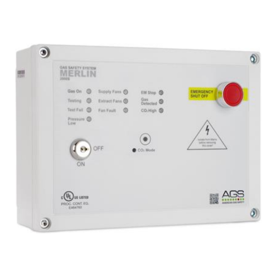
located on the front cover (American Gas Safety Logo).
2. GAS SOLENOID VALVE OUTPUT
100-120V AC electrical power supplied from the [VALVE OUT] connector using a 3 core cable
can be connected to a gas solenoid valve which can shut the gas supply on alarm status.
Refer to your valve manual for more information and wiring!
3. SUPPLY & EXTRACT FAN PRESSURE DIFFERENTIAL SWITCHES / CURRENT MONITORS
These terminals are used to receive an input signal from external air pressure switches or
external current monitors. These terminals have factory fitted links installed.
If only one fan is being used – leave factory fitted links in terminals NOT IN USE!
1500S IOM Rev: 08
01-20
Merlin 1500S
4
