- ページ 5
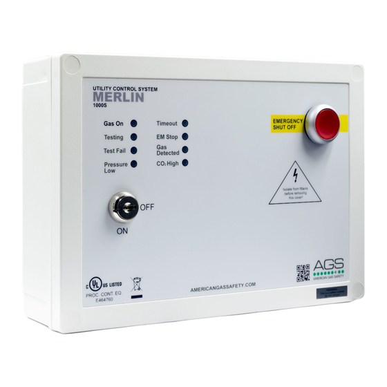
ラボラトリー機器 AGS Merlin 1000SのPDF インストレーション&オペレーションマニュアルをオンラインで閲覧またはダウンロードできます。AGS Merlin 1000S 12 ページ。 Gas utility isolation controller
AGS Merlin 1000S にも: ユーザー・インストール・マニュアル (10 ページ), インストレーション、オペレーション、メンテナンスマニュアル (10 ページ), インストレーション&オペレーションマニュアル (16 ページ)

Installation & Operation Manual
Typical Installation Arrangement
Terminal Connections
1. POWER / LINE IN
110-120V AC Power should be supplied to the [POWER / LINE IN] terminal and fused at 3A.
2. GAS SOLENOID VALVE OUTPUT
110-120V AC electrical power supplied from the [VALVE OUT] connector using a 3 core cable can be
connected to a gas solenoid valve which can shut the gas supply on alarm status.
Pressure sensors should be screwed to the downstream port of the valve.
3. BMS OUTPUT
Connections are available on the board for Building Management Systems.
[NO Normally Open] [COM Common] [NC Normally Closed] These are volt free connections.
This is a relay that changes state in alarm or when the gas is on/off and can be used in conjunction with
the 12V DC output and other external relays that affect other devices and controls such as purge fans
and audible alarms etc. See section; Switch Settings - for BMS options
Rev: 10
02-21
Merlin 1000S
5
