- ページ 4
ソウ HIKOKI CB12-ST2のPDF ハンドリング・インストラクションをオンラインで閲覧またはダウンロードできます。HIKOKI CB12-ST2 16 ページ。 Band saw stand

English
(7) Check that the D6 knob bolt on the rear side is correctly
tightened, and that the main tool unit is securely
installed on the stand. (Fig. 5)
Front side
of the
band saw
Hinge (B)
2. Operating the switch
After installing the band saw on the stand, check that the
switch can be correctly operated.
(1) Check that the band saw stand is correctly secured, and
that the lever switch is in the OFF position. (Fig. 6)
Lever switch
ON
(2) Install the battery on the main tool unit.
(3) Check that the band saw blade is not touching anything,
then turn the lever switch ON and OFF to check that the
band saw operates correctly.
NOTE
The lever switch does not function unless the switch is
held in the ON position using the switch holder.
3. Adjusting the lower limit position of the band saw
blade
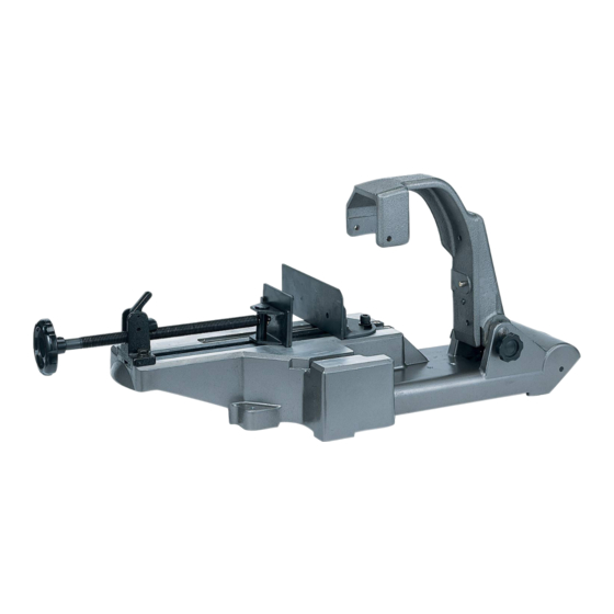
Adjust the positions of the base of the band saw stand
and the tip of the band saw blade. (Fig. 7)
(1) Remove the stopper bolt and screw it several turns into
the screw hole for keeping the stopper bolt.
(2) Slowly move the main tool unit down, and adjust the
position of the guide plate so that the tip of the band saw
blade stops approximately 2 mm below the top surface
of the base. (Use the 4-mm hexagonal wrench supplied
as a standard accessory.)
(3) After fi nishing the adjustment, fi rmly secure the guide
plate using two M6 screws.
Rear side
of the
band saw
Fig. 5
OFF
Fig. 6
Band saw blade
Top surface of the base
4. Adjusting the perpendicularity of the band saw
blade
<Adjustment of the perpendicularity between vise (B) and
the band saw blade (Fig. 8)>
(1) Loosen the two vise (B) adjustment bolts using the 8-mm
hexagonal wrench supplied as a standard accessory.
Ensure that vise (A) is away from vise (B).
(2) Place the vise guide supplied as a standard accessory
as shown in the fi gure. Move the main tool unit down to
lightly press the vise guide against the side of the band
saw blade and the guide plate.
(3) Lightly press the vise guide so that it does not move, and
place vise (B) so that it comes in contact with the vise
guide.
Tighten the two vise (B) adjustment bolts to fi rmly secure
vise (B) in that position.
Vise (A)
Vise guide
Band saw blade
NOTE
If a higher level of cutting precision is required, adjust the
vise position using a speed square.
4
M6 screws
Guide plate
Stopper bolt
Fig. 7
Vise (B)
adjustment bolt
Vise (B)
Guide plate
Fig. 8
