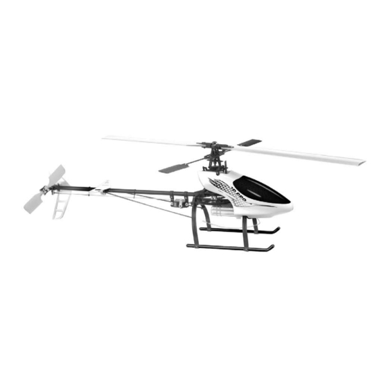
- ページ 4
おもちゃ Century Helicopter Products Hummingbird Elite 3D ProのPDF 組立・取扱説明書をオンラインで閲覧またはダウンロードできます。Century Helicopter Products Hummingbird Elite 3D Pro 12 ページ。
Century Helicopter Products Hummingbird Elite 3D Pro にも: 取扱説明書 (10 ページ)

Section 4: Tail Drive Assembly (Continued)
Bags Used:
CNE308, CNE309, CNE312, CNE216
Tail Boom/Drive II (4-1, 4-2, 4-3)
9) Slide one of the CNE213
Bearing
10) Open parts bag CNE305
CNE305 includes a bag with 3x
into a container or open the bag when it's ready to be use.
11) Get the
Small Beveled Gear
Tail Drive
Shaft. Make sure that the head is flush with the tip of
Drive
Shaft. Place a small amount of locktite on the threads of the
Screw
to secure the
Small Beveled Gear
4-2).
12) Install the
Tail Drive Shaft
Boom
Bracket. Then insert the
Shaft. Use a small amount of locktite to secure the
Drive
eled Gear
in place by using the supplied
13) Using parts bag CNE308
mounts over the
Tail Boom
the screws in CNE308 at this time.
Section 5: Landing Gear & Tail Supports
Bags Used:
CNE326, CNE310, CNE317, CNE316
Landing gear assembly (5-1, 5-2, 5-3)
14) Open CNE326
Landing Gear
inside of the curved portion of the
holes in these posts. When you attach the
all of the holes are pointing to the rear.
15) Use the supplied
M2x11.5 Machine Screws
of the
Landing Struts
to the
the
Rear Lower
Bracket.
16) Insert one
Pushrod Guide
fins bag. Install the
Horizontal Fin
Push Rod
Guides.
17) (This step is related to the assembly in this section but cannot be completed
until 10-2 has been completed). Insert the carbon fiber
the
Mounting Posts
and in to
plied
M2x8 Machine Screw
18) Use the
Rudder Pushrod
in the
Push Rod Guides
.
Put our assemblies to the side for now and we will get back to it later.
5-2
M2x8 Machine
Horizontal fin
Screw #CNE317
#CNE317
4
over the
Tail Drive
Shaft.
Tail Drive Gear
Set.
M2x2 Set
Screws, put these screws
and insert it into the rear section of the
on the
Tail Drive Shaft
into the
Tail Boom
and through the
Large Beveled Gear
onto the
M2x2 Set
Screw.
Rear Rudder Servo
Mounts, insert both
(refer to 4-3 for direction).
Set. Note that
there are mounting posts on the
Landing
Struts. Also notice that there are
Landing Gear
found in CNE310 to mount one
Radio
Tray. The other
Landing Strut
first and then the
Horizontal Fin
onto the CNE316
Tail Boom
Horizontal Fin
Mounting
Posts. Use the sup-
to secure the
Horizontal
Fin.
from bag CNE316 connecting it to the indentations
Pushrod Guide
#CNE316
Tail Boom
#CNE316
4-1
Tail Boom #CNE316
(Rear side with round holes)
4-2
Tail
Set
(see
Tail
Tail
M2x2 Set
Screw
Large Bev-
#CNE305
4-3
Do not tighten
Tail boom
#CNE308 Rear
#CNE316
Rudder Servo
Mounts
Set, make sure that
connects to
from CNE317 3D
between the
Mounting Posts
(For boom supports
Tail Boom Support
to
pointing rearward)
Tail Boom Supports
#CNE317
5-3
Tail Drive Shaft
#CNE315
Bearing
#CNE213
Small Beveled
Tail Drive Gear
#CNE305
Large Beveled
Tail Drive Gear
#CNE305
5-1
Rear Lower
Bracket
#CNE310
M2x11.5 Machine
Screws
#CNE326
(Landing Gear)
Rudder Pushrod
#CNE316
Note: Only Do step (5-3)
after completing (10-2)
M2x2 Set Screw
#CNE305
Tail Drive Shaft (must sit
flush with the large beveled
gear) #CNE315
Radio Tray
#CNE310
Landing Struts
(Plastic)
#CNE326
Landing Skids
(Aluminum)
#CNE326
Pushrod Guide
#CNE316
Horizontal Fin and clamp
with Mounting Posts for
boom supports #CNE317
