- ページ 7
ヒーター Empire SR-18T-2のPDF 取付説明書および取扱説明書をオンラインで閲覧またはダウンロードできます。Empire SR-18T-2 18 ページ。 Unvented
2"
(511mm)
(51)
1 3/32"
(28mm)
18 7/8"
(479mm)
4 1/32
2 1/32" (52mm)
(102mm)
MIN
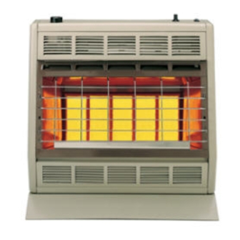
Figure 7 (SR-30T)
On Solid Wall
1. After locating mounting holes, attach (4) #10 x 1" (25mm)
screws provided into the wall. Do not completely tighten
screwheads to the wall, leave a 1/8" (3mm) gap between
screwheads and wall.
2. Mount heater onto the (4) screwheads and complete tightening
screwheads into the wall.
Attention! Use the following steps to properly align the upper
louver and the reflector with the heat shield.
a. When replacing upper louver, be sure the bottom lip of upper
louver goes behind the heat shield.
b. When replacing reflector, be sure the top lip of reflector goes in
front of the heat shield.
3. Connect the gas line.
On Sheet Rock Wall
1. After locating mounting holes, drill (4) 5/16" (8mm) diameter
holes into the wall.
2. Insert (4) plastic expansion anchors provided into the holes.
3. Tighten (4) #10 x 1" (25mm) screws provided into the plastic
expansion anchors. Do not completely tighten screwheads to
the plastic expansion anchors, leave a 1/8" (3mm) gap between
screwheads and plastic expansion anchors.
4. Mount heater onto the (4) screwheads and complete tightening
the screwheads to the plastic expansion anchors.
Attention! Use the following steps to properly align the upper
louver and the reflector with the heat shield.
a. When replacing upper louver, be sure the bottom lip of upper
louver goes behind the heat shield.
b. When replacing reflector, be sure the top lip of reflector goes in
front of the heat shield.
5. Connect the gas line.
Optional Floor Stand Installation* (Figure 8)
1. Align clearance holes on floor stand with screw holes on bottom of
heater, as shown in Figure 8.
2. Attach floor stand to heater with (4) screws provided with floor
stand.
3. Connect the gas line.
*Floor stand can not be used in a bedroom installation. SR-10T must be
wall mounted in a bedroom installation.
R-5210
24 1/8"
(613mm)
20 1/8"
2"
(51)
(559mm)
2" (51mm) MIN
22"
Installation on Rugs and Tile
If this appliance is installed directly on carpeting, tile or other combus-
tible material, other than wood flooring, the appliance shall be installed
on a metal or wood panel extending the full width and depth of the
appliance.
Attention: Optional Floor Stand meets requirement.
The base referred to above does not mean the fire-proof base as used on
wood stoves. The protection is for rugs that are extremely thick and
light colored tile.
Gas Supply (Figure 9)
Check all local codes for requirements, especially for the size and type
of gas supply line required. Note: Never use plastic pipe. Check to
confirm whether your local codes allow copper tubing or galvanized.
3 9/16"
(90mm)
1 11/16" (43mm)
TO WALL
Dimensions Apply to SR-10T, SR-18T and SR-30T
Installing a New Main Gas Cock
Each appliance should have its own manual gas cock.
A manual main gas cock should be located in the vicinity of the unit.
Where none exists, or where its size or location is not adequate, contact
your local authorized installer for installation or relocation.
SR-30T SHOWN
Figure 8
Figure 9
Page 7