- ページ 9
ヒーター Empire SR-18T-2のPDF 取付説明書および取扱説明書をオンラインで閲覧またはダウンロードできます。Empire SR-18T-2 18 ページ。 Unvented
9. Remove heater from wall.
10. Remove gas valve bracket from casing assembly (4 screws to be
removed are located on casing assembly back).
11. Remove hydraulic thermostat bulb from thermostat bulb clip
located at casing assembly bottom.
12. Remove gas valve from gas valve bracket.
13. As parts are being replaced in reverse order, check for gas leaks at
all gas connections before upper louver, reflector and lower louver
are replaced onto casing assembly.
Removing Main Burner From Casing Assembly
1. Turn OFF gas supply to the heater.
2. Turn OFF electrical supply to the heater if optional blower is
installed in heater.
3. Remove lower louver from casing assembly (2 screws).
4. Remove reflector from casing assembly (2 screws).
5. Disconnect supply tubing from orifice holder(s).
6. Remove pilot bracket from main burner assembly (2 screws).
7. Remove main burner assembly from casing assembly (4 screws).
8. Remove orifice shield from main burner assembly. Attach orifice
shield to new main burner assembly.
9. As parts are being replaced in reverse order, check for gas leaks at
all gas connections before lower louver is replaced onto casing
assembly.
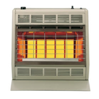
SR-10T, SR-18T and SR-30T Main Burner Flame (Figure11)
The main burner flame will have a red-orange glow over the surface of
the ceramic plaques. A few small, hairline cracks may form over the
surface of the ceramic plaques or at the edges of the ceramic plaques
where they have been cemented into position on the burner assembly
frame. These small, hairline cracks will not affect the operation or
performance of the ceramic plaques. Only, when large cracks develop,
with blue flames escaping from the large cracks, should you contact your
QUALIFIED SERVICE PERSON.
A red-orange haze that is visible on the ceramic plaques is acceptable.
A blue flame that rolls out at the top of the ceramic plaques indicates an
accumulation of dust, lint or spider webs inside the casing assembly and
main burner assembly. Use the following procedure to inspect the casing
assembly and main burner assembly.
1. Turn OFF gas supply to the heater.
2. Turn OFF electric supply to the heater if optional blower is installed
in heater.
3. Remove lower louver from casing assembly ( 2 screws).
4. Remove reflector from casing assembly (2 screws).
5. Inspect interior of casing assembly for accumulation of dust, lint or
spider webs. If necessary, clean interior of casing assembly with a
vacuum cleaner or apply air pressure. Do not damage any components
within casing assembly when you are cleaning.
6. Remove pilot bracket from main burner assembly (2 screws).
7. Pivot pilot bracket with attached pilot away from main burner
assembly (do not damage pilot tubing).
8. Inspect main burner orifice(s) through the rectangular opening(s) in
the venturi (throat) of the main burner(s). Dust, lint and spider webs
can accumulate on top of the main burner orifice(s). If necessary,
clean main burner orifice(s) with a vacuum cleaner or apply air
pressure. To thoroughly clean the main burner orifice(s) proceed to
Step 9.
9. Disconnect supply tubing from orifice holder(s).
10. Remove orifice holder from venturi of main burner assembly (1
screw for each orifice holder).
11. Remove main burner orifice from orifice holder.
12. Apply air pressure through main burner orifice and orifice holder to
remove dust, lint or spider webs.
13. Apply air pressure into ceramic plaque(s) to remove dust, lint or
spider webs.
14. As parts are being replaced in reverse order, check for gas leaks at
all gas connections before lower louver is replaced onto casing
assembly.
R-5210
SR-30T SHOWN
Figure 11
Proper Pilot Flame (Figure 12)
The correct flame will be blue and will extend beyond the thermocouple.
The flame will surround the thermocouple just below the tip. A slight
yellow flame may occur where the pilot flame and main burner flame
meet.
Figure 12
Oxygen Depletion Sensor Pilot (Figure 13)
When the pilot has a large yellow tip flame, clean the Oxygen Depletion
Sensor as follows:
1.
Clean the ODS pilot by loosening nut B from the pilot tubing. When
this procedure is required, grasp nut A with an open end wrench.
2.
Blow air pressure through the holes indicated by the arrows. This
will blow our foreign materials such as dust, lint and spider webs.
Tighten nut B also by grasping nut A.
Figure 13
Page 9