- ページ 18
アビオニクス・ディスプレイ Garmin G500のPDF マニュアルをオンラインで閲覧またはダウンロードできます。Garmin G500 40 ページ。 Primary flight and multifuction display system
Garmin G500 にも: クイック・リファレンス (2 ページ), 取扱説明書 (14 ページ)

2.7
Navigation Angle
The GDU 620 Navigation Angle can be set to either True or Magnetic on the
AUX page. The Navigation Angle defines whether the GDU 620 headings are
referenced to True or Magnetic North. The Navigation Angle set in the GDU
620 must match that which is set on all GPS/SBAS navigators interfaced to the
unit.
2.8
AHRS Normal Operating Mode
The Attitude and Heading Reference System integrity monitoring features
require the availability of GPS and Air Data. Although the attitude will remain
valid if one of these systems becomes inoperative, IFR flight is not authorized
unless both integrity systems are fully operational. The G500 monitors these
integrity systems automatically and will alert the pilot when the AHRS is not
receiving GPS or Air Data. Note: In dual GPS installations, only one GPS needs
to be available for IFR use.
2.9
Airspeed Limitations and Indicator Markings
The original type design approved airspeed limitations remain in effect. The
airspeed limitations imposed by the AFM/POH, standby airspeed indicator
and/or airspeed limitation placards must be observed.
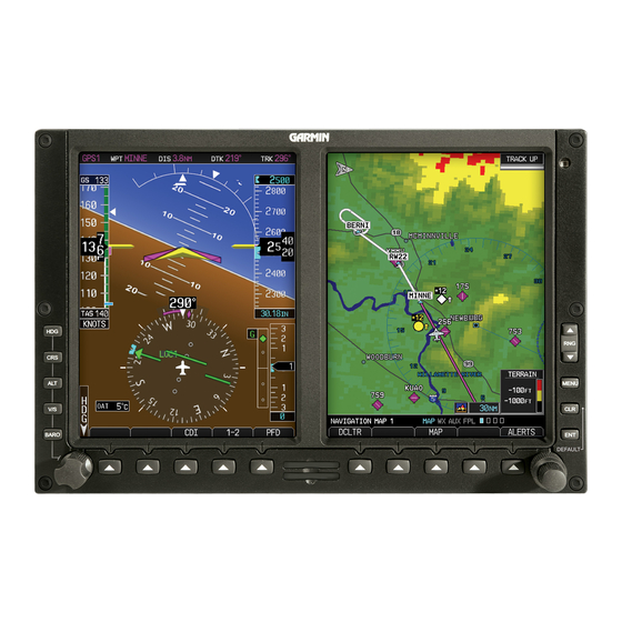
The G500 airspeed tape displays red/white striping to indicate the maximum
allowable airspeed (V
is configured to indicate the appropriate maximum allowable airspeed for the
airplane, including variations for altitude or Mach number.
The G500 airspeed tape displays a red low-speed awareness band at the lower
range of the airspeed tape. This low-speed awareness band is configured to a
fixed value. It does not indicate an actual or calculated stall speed and does not
adjust with variations in aircraft weight or other factors.
All other G500 airspeed tape indications are configured to indicate the original
type design limitations. The G500 airspeed tape does not adjust these additional
markings (including V
with aircraft weight, altitude, or other factors.
2.10 Aerobatic Maneuvers
Conducting aerobatic maneuvers may cause the attitude information displayed
on the G500 to be incorrect or temporarily removed from the display.
2.11 Electric Standby Attitude Gyro
If an electric standby attitude gyro is installed, the gyro operates from the
aircraft electrical system with a dedicated emergency battery specific to the
electric gyro. The electric attitude gyro battery capacity may vary considerably
depending on temperature, charge status, and battery life condition. Low
temperatures below 32°F will temporarily degrade battery capacity. Internal
chemistry will slowly degrade battery capacity over several years of operation
even when correctly maintained. A poorly maintained battery will suffer
AFMS, GARMIN G500 PFD/MFD SYSTEM
FAA APPROVED
/V
/M
). This maximum allowable airspeed display
NE
MO
MO
, landing gear, or flap speed limitations) for variations
NO
190-01102-01 Rev. 9
Page 18 of 40
