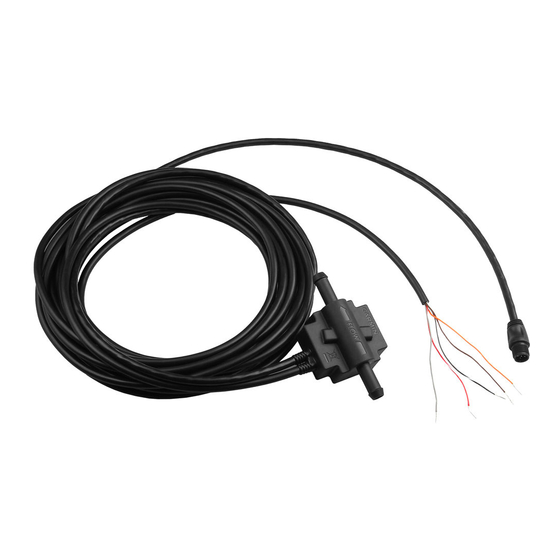
舶用機器 Garmin GFS 10 - Fuel SensorのPDF 取付説明書をオンラインで閲覧またはダウンロードできます。Garmin GFS 10 - Fuel Sensor 49 ページ。 Fuel sensor
Garmin GFS 10 - Fuel Sensor にも: クイック・リファレンス・マニュアル (24 ページ), テクニカル・リファレンス (30 ページ), 取付説明書 (44 ページ), 重要な安全情報 (48 ページ), 設定マニュアル (2 ページ), 適合宣言 (1 ページ)

To obtain the best possible performance, install your GFS 10 Fuel Sensor according to the following instructions. If you experience difficulty
during the installation, contact Garmin Product Support, or seek the advice of a professional installer.
The GFS 10 will communicate with NMEA 2000- or Garmin CANet-compatible chartplotters and displays. Refer to
of compatible devices.
The GFS 10 is designed for use with gasoline-engine fuel systems. Do not use the GFS 10 with diesel-engine fuel systems.
WARNING: See the Important Safety and Product Information guide in the product box for product warnings and other
important information.
Product Registration
Help us better support you by completing our online registration at www.garmin.com/registration/.
For future reference, write the serial number assigned to your GFS 10 in the space provided. It is located on a sticker on the back of the unit and
a sticker around the cable.
Serial number
Contact Garmin
Contact Garmin if you have any questions while installing or using your GFS 10. In the USA contact Garmin Product Support by phone:
(913) 397-8200 or (800) 800-1020, Monday–Friday, 8 am–5 pm Central Time; or go to www.garmin.com/support/.
In Europe, contact Garmin (Europe) Ltd. at +44 (0) 870.8501241 (outside the UK) or 0808 2380000 (within the UK).
Packing List and Accessories
Before installing your unit, confirm that your package includes the following items. If any parts are missing, contact your Garmin dealer
immediately.
Standard Package
•
GFS 10 Fuel Sensor unit
•
4 reusable stainless-steel hose clamps
•
" In-line fuel filter
/
3
8
•
Mounting hardware
•
CANet adapter
•
NMEA 2000 T-connector and terminators
•
Installation instructions
Installing the GFS 10
Step 1: Install the GFS 10 in the fuel line.
Step 2: Mount the GFS 10 and fuel filter.
Step 3: Connect the GFS 10 to the power source and the fuel gauge.
Step 4: Connect the GFS 10 to your chartplotter or marine instrument.
Step 5: Update your chartplotter.
January 2008
GFS 10 Fuel Sensor Installation Instructions
Optional Accessories
•
Additional NMEA 2000 network components
•
CANet kit
Tools Needed
•
Hose cutter or knife (to cut the fuel line)
•
Flathead screwdriver (to tighten the hose clamps)
•
Drill and drill bits (to install the mounting hardware)
190-00884-90 Rev. A
www.garmin.com
for a list
Printed in Taiwan
