- ページ 9
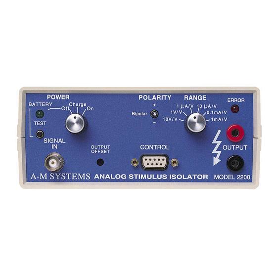
コントロールユニット A-M Systems 2200のPDF 取扱説明書をオンラインで閲覧またはダウンロードできます。A-M Systems 2200 19 ページ。 Analog stimulus isolator

Examples and Applications
The first thing that should be done in any use of this instrument is to check the batteries
using the internal battery test function. Set the Power switch set to Off, and push the
Battery/Test push-button. The Battery OK light should come on, indicating an adequate
charge. If the test light does not come on, the batteries need to be recharged. The
following applications assume that this simple test has been passed first.
Monophasic Output Pulse
An example of a simple application (and basic instrument test) is using a pulse generator,
function generator, or other source of TTL-compatible voltages to provide an On/Off signal.
Control/Connector
Output
Input
Sign
Range
Power
You should observe the same waveform on both input and output. Rotating the DC offset
control on the function generator should cause the DC level to change equally in input and
output.
Change the Range control to 1mA/V. The waveform should stay the same. Now turn the
Power off, disconnect the 1kW resistor, and turn the Power back on. The output waveform
should be much larger (flattening against the power supply rails), and the error LED should
light up as the 2200 fails to drive up to 6500mA into the high impedance of the oscilloscope
input/load.
A-M Systems
Setting
Connect a 10kohm resistor to the output
Connect an oscilloscope probe across the resistor.
Connect a function generator with a 1kHz 1V p-p sine wave
Bipolar
1V/V
On
PO BOX 850, Carlsborg, WA 98324 USA
Telephone: 800-426-1306 * 360-683-8300 * FAX: 360-683-3525
E-mail: [email protected] * Website: http://www.a-msystems.com
6
