- ページ 6
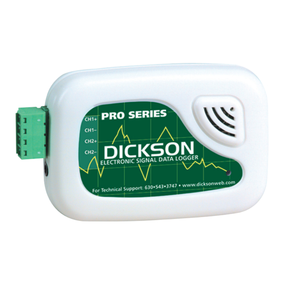
データロガー Dickson ES120のPDF マニュアルをオンラインで閲覧またはダウンロードできます。Dickson ES120 9 ページ。 Electronic signal data logger

Operating Instructions
• Install the DicksonWare™ Software.
• Connect the cable (supplied with the software) to the logger and to a working serial port on your
computer.
ES120 Setup
• Ensure dip switch settings. Remove the screw on the back of the case and position the switch for each
channel according to the type of signal being supplied, ON for 0 to 20mA Current signal and OFF
for 0 to 5Vdc signal.
• Connect your 0 to 5Vdc and/or 0 to 20mA transmitter(s) using the channel polarity indicated on the
front label.
ES120A Setup
• Connect your 0 to 15Vdc source or transmitter(s) using channel polarity indicated on the front label.
DO NOT CHANGE DIP-SWITCH SETTINGS FOR ES120A.
Getting Started
• Click the Setup button. When the setup window appears, all fields should be automatically filled in, this
will confirm that DicksonWare™ has recognized the logger. Should all fields remain blank, refer to "No
Communication" in the Trouble Shooting section of this manual.
• Once DicksonWare™ recognizes the logger, select the channels tab. Press the adjust button next to the
desired channel which will bring up a channel adjustment window with two categories, ENABLE and
USER DEFINED. In the "Enable" section, the "Enable" box should be deselected. If a channel is not
going to be used, this will allocate all storage capacity to the active channel. You may also choose to
change the label for that channel to reflect the actual variable being measured such as Temperature,
Pressure or Flow.
Following Setups Are For ES120 Models Only
In the "User Defined" section, set the MIN and MAX input signal being supplied by your transmitter, units
should show mA or V depending on what type of signal that channel is setup to receive. Now set the MIN
and MAX range that applies to the programmed input signal.
Changing these parameters in the ES120A model will cause the logger to operate improperly.
You may also want to type a variable in the units field that represents what is being measured such as F for
Fahrenheit, PSI for pressure or gpm for gallons per minute. You may set the units for model ES120A as well.
• To start logging, press the Clear button. This will delete all data currently stored.
• The logger is now sampling and ready for use. The default sample interval is 1 minute. Verify that the
indicator light is flashing every 10 seconds. You may choose to change Default settings for sample
interval and start-date and time. When changing these settings, the logger will automatically go
through the clear process to accept your changes.
NOTE: To conserve battery life when storing unit, press the Setup button and select the shortest Sample
Interval and Stop When Full in the Samples section.
Rev. 02/06
