- ページ 14

産業機器 Siemens SIMATIC ET 200ALのPDF 設備マニュアルをオンラインで閲覧またはダウンロードできます。Siemens SIMATIC ET 200AL 28 ページ。 10-link digital output module dq 8x24vdc/2a 8xm12
Siemens SIMATIC ET 200AL にも: マニュアル (38 ページ), マニュアル (50 ページ), マニュアル (38 ページ), マニュアル (32 ページ), マニュアル (37 ページ), 設備マニュアル (46 ページ), マニュアル (26 ページ), 設備マニュアル (27 ページ), マニュアル (25 ページ)
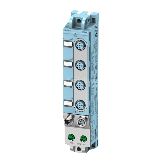
Siemens SIMATIC ET 200AL 設備マニュアル
3.2

Pin assignment

Note
Color coding
The sockets for ET-Connection and the power supply of the modules are color-coded. These
colors correspond to the colors of the offered cables.
Pin assignment of the sockets for digital outputs
The tables below show the pin assignments of the 8 sockets for connection of the digital
outputs.
Table 3- 1
Pin
1
2
3
4 *
5
* The outputs DQ
Digital output module DQ 8x24VDC/2A 8xM12 (6ES7142-5AF00-0BA0)
Equipment Manual, 08/2021, A5E36683723-AB
Pin assignment for digital outputs
Assignment
X10 to X17 sockets for digital outputs
Unassigned
Unassigned
X10 - X13: Ground 1M
X14 - X17: Ground 2M
Output signal DQ
: Connector X10
0
Output signal DQ
: Connector X11
1
Output signal DQ
: Connector X12
2
Output signal DQ
: Connector X13
3
Output signal DQ
: Connector X14
4
Output signal DQ
: Connector X15
5
Output signal DQ
: Connector X16
6
Output signal DQ
: Connector X17
7
Functional earth FE
to DQ
are connected to 1L+; the outputs DQ
0
3
3.2 Pin assignment
Front view of the sockets
X10, X12, X14,
X11, X13, X15,
X16
to DQ
are connected to 2L+.
4
7
Wiring
X17
13