Siemens SIMATIC ET 200AL 장비 매뉴얼 - 페이지 14

{카테고리_이름} Siemens SIMATIC ET 200AL에 대한 장비 매뉴얼을 온라인으로 검색하거나 PDF를 다운로드하세요. Siemens SIMATIC ET 200AL 28 페이지. 10-link digital output module dq 8x24vdc/2a 8xm12
Siemens SIMATIC ET 200AL에 대해서도 마찬가지입니다: 매뉴얼 (38 페이지), 매뉴얼 (50 페이지), 매뉴얼 (38 페이지), 매뉴얼 (32 페이지), 매뉴얼 (37 페이지), 장비 매뉴얼 (46 페이지), 매뉴얼 (26 페이지), 장비 매뉴얼 (27 페이지), 매뉴얼 (25 페이지)
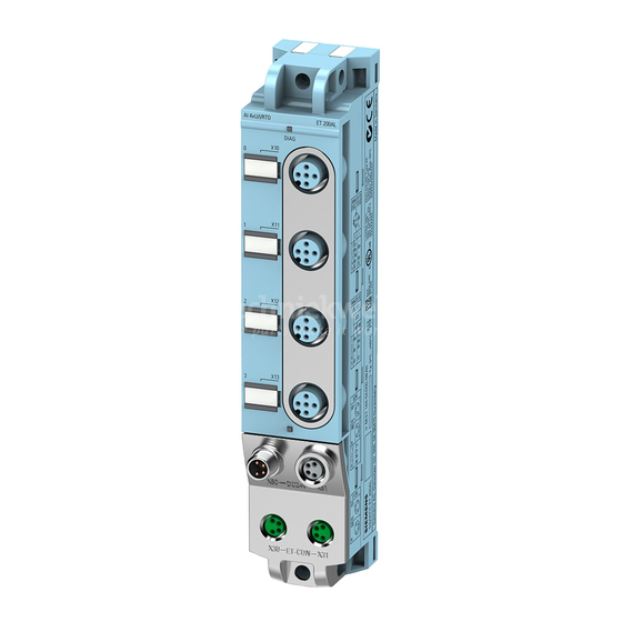
Siemens SIMATIC ET 200AL 장비 매뉴얼
3.2

Pin assignment

Note
Color coding
The sockets for ET-Connection and the power supply of the modules are color-coded. These
colors correspond to the colors of the offered cables.
Pin assignment of the sockets for digital outputs
The tables below show the pin assignments of the 8 sockets for connection of the digital
outputs.
Table 3- 1
Pin
1
2
3
4 *
5
* The outputs DQ
Digital output module DQ 8x24VDC/2A 8xM12 (6ES7142-5AF00-0BA0)
Equipment Manual, 08/2021, A5E36683723-AB
Pin assignment for digital outputs
Assignment
X10 to X17 sockets for digital outputs
Unassigned
Unassigned
X10 - X13: Ground 1M
X14 - X17: Ground 2M
Output signal DQ
: Connector X10
0
Output signal DQ
: Connector X11
1
Output signal DQ
: Connector X12
2
Output signal DQ
: Connector X13
3
Output signal DQ
: Connector X14
4
Output signal DQ
: Connector X15
5
Output signal DQ
: Connector X16
6
Output signal DQ
: Connector X17
7
Functional earth FE
to DQ
are connected to 1L+; the outputs DQ
0
3
3.2 Pin assignment
Front view of the sockets
X10, X12, X14,
X11, X13, X15,
X16
to DQ
are connected to 2L+.
4
7
Wiring
X17
13