- ページ 24

産業機器 Siemens SIMATIC ET 200SのPDF マニュアルをオンラインで閲覧またはダウンロードできます。Siemens SIMATIC ET 200S 28 ページ。 Distributed i/o digital electronic module 4do dc24v/2a hf
Siemens SIMATIC ET 200S にも: 取扱説明書 (18 ページ), マニュアル (16 ページ), ユーザーマニュアル (16 ページ), ユーザーマニュアル (26 ページ), マニュアル (37 ページ), マニュアル (24 ページ), 機能マニュアル (40 ページ), 操作説明 (4 ページ), オリジナル取扱説明書 (19 ページ), オリジナル取扱説明書 (20 ページ), マニュアル (34 ページ), マニュアル (14 ページ), マニュアル (24 ページ), オリジナル取扱説明書 (17 ページ), オリジナル取扱説明書 (19 ページ), マニュアル (16 ページ), マニュアル (12 ページ), マニュアル (32 ページ), マニュアル (18 ページ), マニュアル (12 ページ), マニュアル (28 ページ), マニュアル (22 ページ), マニュアル (22 ページ), マニュアル (36 ページ), マニュアル (16 ページ)
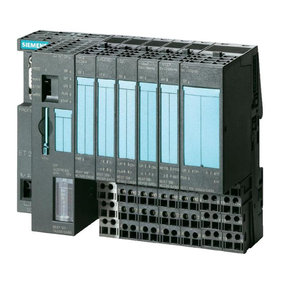
Siemens SIMATIC ET 200S マニュアル
Connecting
5.1 Connecting measuring sensors
Abbreviations used
The meanings of the abbreviations in the figures below are as follows:
M +
M-
M
ANA
M
L+
U
CM
U
ISO
Isolated measuring sensors
The isolated measuring sensors are not connected to the local ground potential. These can
be potential-free. Depending on local conditions or interference, potential differences U
(static or dynamic) can occur between the measuring lines M- of the input channels and the
reference point of the measuring circuit M
In environments with a high level of EMC interference, it is advisable to connect M- to M
in order to prevent the permissible U
The following schematic representation illustrates the connection of isolated measuring
sensors to the analog input modules.
5
24
Measuring line (positive)
Measuring line (negative)
Analog measuring circuit reference potential
Ground connection
Rated load voltage 24 V DC
Potential difference between inputs
Potential difference between M- and central grounding point
mA
mA
4
Logic
Backplane bus
Ground bus
Central grounding point
Isolated measuring sensors
.
ANA
value from being exceeded.
CM
1
3
2AI I 4WIRE HS analog electronic module (6ES7134-4GB62-0AB0)
2
Manual, 01/2008, A5E01076124-02
CM
ANA