- ページ 8
スイッチ Siemens Sitrans WM100のPDF 取扱説明書をオンラインで閲覧またはダウンロードできます。Siemens Sitrans WM100 22 ページ。 Motion sensing switch
Siemens Sitrans WM100 にも: 取扱説明書 (16 ページ)

Installing/mounting
Environment
The WM100 must be mounted in an area that is non-hazardous, within the ambient
temperature range and non-corrosive to the materials of construction. Refer to Dimensions
(Page 17) for materials of construction.
①
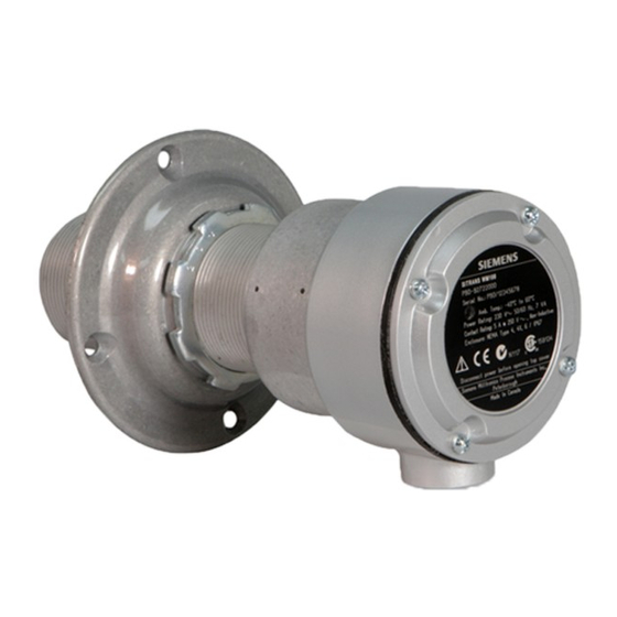
The probe should be mounted using the supplied mounting flange, onto a vibration free
structure. The gap between the probe and the target should be sufficient such that there is
no danger of the target damaging the probe. The maximum allowable gap ranges from 20
mm to over 100 mm from the face of the target to the face of the probe. The range is
dependent on the target type and range of speed expected. See typical performance graphs
(Page 13) for examples.
The WM100 is sensitive to lateral disturbances to its magnetic field. If the WM100 is
responding to motion from an interfering target, move the WM100 or install a ferrous plate
(steel) as a shield between the WM100 and the interfering target.
Where possible, the probe should be mounted so the conduit entry is pointing down to avoid
accumulation of condensation in the casing. Connection of the probe should be made via
flexible conduit for easier removal or adjustment of the probe.
Note
In climates where direct sunlight may cause the SITRANS WM100 temperature to rise above
the specified limit, shade the unit by installing a sun shield.
8
Up to 100 mm (4") maximum gap
Operating Instructions, 07/2017, A5E45103494-AA
SITRANS WM100
