- ページ 10
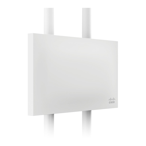
無線アクセスポイント Cisco MERAKI MR72のPDF インストレーション・マニュアルをオンラインで閲覧またはダウンロードできます。Cisco MERAKI MR72 20 ページ。
Cisco MERAKI MR72 にも: ハードウェア・インストール・マニュアル (16 ページ)

Powering the MR72 with an 802.3af Power over Ethernet Switch
Route Ethernet cable from a port on an active 802.3af PoE switch to the Eth0 port in the bay of the MR72. The MR72 is
Gigabit Ethernet-capable. To maximize device performance, a Gigabit-capable switch should be used.
Verify Device Functionality and Test Network Coverage
1. Check LEDs
a. The Power LED should be solid green (or blue, if clients are connected). If it is flashing blue, the firmware is
automatically upgrading and the LED should turn green when the upgrade is completed (normally within a
few minutes). See the
b. Note: Your MR72 must have an active route to the Internet to check and upgrade its firmware.
2. Verify access point connectivity
a. Use any 802.11 client device to connect to the MR72 and verify proper connectivity using the client's web
browser.
3. Check network coverage
4. Confirm that you have good signal strength throughout your coverage area. You can use the signal strength meter
on a laptop, smart phone, or other wireless device.
Troubleshooting
Reference the
MR Product Page
Regulatory Information
Europe – EU Declaration of Conformity
This device complies with the essential requirements of the R&TTE Directive 1999/5/EC. The following test methods
have been applied in order to prove presumption of conformity with the essential requirements of the R&TTE Directive
1999/5/EC:
Radio: EN 300 328, EN 301 893
EMC: EN 301 489-1, EN 301 489-17
Safety: EN 60950-1
Exposure: EN 505385
Emissions: EN 55022, EN 61000-3-2,
EN 61000-3-3
Immunity: EN 61000-4-2, EN 61000-4-3,
EN 61000-4-4, EN 61000-4-5,
EN 61000-4-6, EN 61000-4-11
"LED
Indicators" section for more details. .
for additional information and troubleshooting tips.
10
