- ページ 9
ビデオカメラ Sony CCU-790PのPDF 操作マニュアルをオンラインで閲覧またはダウンロードできます。Sony CCU-790P 18 ページ。 Camera control unit
Sony CCU-790P にも: パンフレット&スペック (14 ページ)

Internal Parts and Internal Boards
Note
To reduce the risk of electric shock, fire or injury, do not
open the cabinet. To adjust the internal settings or to
replace the fuses, refer to qualified service personnel.
CABLE
ALARM
d Fuses
Internal parts
a Headset microphone switch 1 (S52)
Set the switch according to the type of microphone of the
headset connected to the INTERCOM/TALLY/PGM
connector on the rear panel of this unit.
CARBON: Carbon microphone (power supply, 20 dB
gain)
ECM: Electret condenser microphone (power supply, 40
dB gain)
DYNAMIC: Dynamic microphone (no power supply, 60
dB gain) (factory-setting)
b INCOM (intercom) selector
Selects the pathway of intercom signals output/input
through the INCOM/TALLY/PGM connector.
PROD: Producer line.
PRIV: Producer line and engineer line are cut off and
communication is possible only between the CCU-
790/790P and the camera connected to the rear panel
of the CCU-790/790P.
ENG: Engineer line. The settings regarding the output
intercom signals can be performed on the internal AU
board. For details, consult your Sony service
personnel.
a Headset microphone switch 1 (S52)
b INCOM selector
c Headset microphone switch 2 (S53)
ON
MIC
OFF
SHORT
OPEN
PGM
MAIN
CAMERA
INTERCOM
POWER
POWER
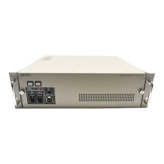
The following parts and boards are located inside the unit,
behind the front panel.
Internal boards
c Headset microphone switch 2 (S53)
When the headset microphone switch 1 (S52) is set to
DYNAMIC, set this switch according to the type of output
of the headset microphone.
GND: Unbalanced type (factory-setting)
OPEN: Balanced type
d Fuses
When the fuses need to be replaced, consult your Sony
service personnel.
Internal boards
For details on the internal boards, consult your Sony
service personnel.
Internal Parts and Internal Boards
9
