- ページ 11
ネットワーク・ハードウェア Cisco ATA 191のPDF ユーザーマニュアルをオンラインで閲覧またはダウンロードできます。Cisco ATA 191 30 ページ。 Analog telephone adapter
Cisco ATA 191 にも: ユーザーマニュアル (30 ページ), 管理マニュアル (4 ページ), ユーザーマニュアル (10 ページ), スタート (8 ページ), マニュアル (10 ページ), クイック・スタート・マニュアル (13 ページ), セットアップマニュアル (6 ページ), ユーザーマニュアル (40 ページ)
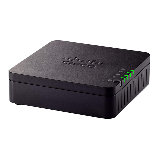
Get Started with Your New ATA
Warning
Wall Mounting
The ATA has two wall-mounted slots on the bottom panel. To mount the ATA on a wall, you need mounting
hardware (not included). Suggested hardware is illustrated (not true to scale).
Recommended hardware (not included): Two #6 pan head, 5/8 in., self-tapping screws with anchors for
sheet rock installation.
Note
Procedure
Step 1
Determine where you want to mount the unit. Verify that the surface is smooth, flat and dry.
Step 2
Drill two pilot holes into the surface 58 mm apart (about 2.28 in.).
Step 3
Insert a screw into each hole, leaving a gap of 5 mm (0.1968 in.) between the underside of each screw head
and the surface of the wall.
Step 4
Place the unit wall-mount slots over the screws and slide the unit down until the screws fit snugly into the
wall-mount slots.
Do not place anything on top of the ATA; excessive weight could damage it.
Insecure mounting might damage the ATA or cause injury. Cisco is not responsible for damages incurred
byinsecure wall-mounting.
Cisco ATA 191 Analog Telephone Adapter User Guide for Cisco Unified Communications Manager
Wall Mounting
7