- ページ 3
コントロールユニット FIRETRACE 800095-AのPDF インストレーション・マニュアルをオンラインで閲覧またはダウンロードできます。FIRETRACE 800095-A 18 ページ。 Dual pressure switch module with & without bypass
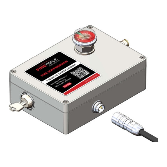
Table of Contents
FOREWORD ..................................................................................................................................................................... 1
1
Warnings ............................................................................................................................................................... 1
1.1
Safety Precautions .................................................................................................................................................. 1
1.2
GENERAL ........................................................................................................................................................................ 2
2
Description ............................................................................................................................................................. 2
2.1
Variants ................................................................................................................................................................. 2
2.2
Product Dimensions ................................................................................................................................................ 2
2.3
With Bypass Key Switch .................................................................................................................................... 2
2.3.1
2.3.2
Standard (without Bypass) ................................................................................................................................. 3
Specifications ......................................................................................................................................................... 3
2.4
2.4.1
Electrical ......................................................................................................................................................... 3
Environmental .................................................................................................................................................. 3
2.4.2
INSTALLATION ................................................................................................................................................................. 4
3
Opening the Module ................................................................................................................................................ 4
3.1
With Bypass Key Switch .................................................................................................................................... 4
3.1.1
Standard (without Bypass) ................................................................................................................................. 5
3.1.2
Configuring the Module ............................................................................................................................................ 5
3.2
Configuration Testing .............................................................................................................................................. 6
3.3
Closing the Module.................................................................................................................................................. 8
3.4
With Bypass Switch .......................................................................................................................................... 8
3.4.1
Standard (without Bypass) ................................................................................................................................. 8
3.4.2
Mounting the Module ............................................................................................................................................... 8
3.5
Direct Mounting ................................................................................................................................................ 9
3.5.1
Flange Mounting Kit .......................................................................................................................................... 9
3.5.2
Magnetic Mounting Kit..................................................................................................................................... 10
3.5.3
Wiring the Module ................................................................................................................................................. 10
3.6
System Activation ................................................................................................................................................. 11
3.7
SERVICE AND MAINTENANCE .......................................................................................................................................... 12
4
General ................................................................................................................................................................ 12
4.1
Post Discharge, System Recharge, and Return to Service .......................................................................................... 12
4.2
5
APPENDIX A................................................................................................................................................................... 13
Table of Figures
Figure 1 - Bypass Variant Envelope Dimensions | Top View ............................................................................................................................................. 2
Figure 2 - Bypass Variant Envelope Dimensions | Side View ............................................................................................................................................ 3
Figure 3 - Standard Variant Envelope Dimensions | Top View .......................................................................................................................................... 3
Figure 4 - Standard Variant Envelope Dimensions | Side View ......................................................................................................................................... 3
Figure 5 - Environmental Limitations ................................................................................................................................................................................. 3
Figure 6 - Exploded View | with Bypass ............................................................................................................................................................................. 4
Figure 7 - Exploded View | Standard ................................................................................................................................................................................. 5
Figure 8 - Configuration Board Overview........................................................................................................................................................................... 5
Figure 9 - Switch Position Details ...................................................................................................................................................................................... 6
Figure 10 - Threaded Insert ............................................................................................................................................................................................... 8
Figure 11 - Threaded Insert Dimensions ........................................................................................................................................................................... 9
Figure 12 - Flange Mounting Kit......................................................................................................................................................................................... 9
Figure 13 - Flanges Installed ........................................................................................................................................................................................... 10
Figure 14 - Magnetic Mounting Kit ................................................................................................................................................................................... 10
Figure 15 - Magnets Installed .......................................................................................................................................................................................... 10
Figure 16 - Cable Harness Install | Exploded View .......................................................................................................................................................... 11
Figure 17 - Harness Pinout Diagram ............................................................................................................................................................................... 11
DIOM 800095-A
ii
7/22/2022