- ページ 9
ロックス Directed XpressKit DBALLのPDF マニュアルをオンラインで閲覧またはダウンロードできます。Directed XpressKit DBALL 14 ページ。 Ford5 remote start ready (rsr) installation
Directed XpressKit DBALL にも: インストレーション・マニュアル (16 ページ), インストレーション・マニュアル (16 ページ), マニュアル (19 ページ)

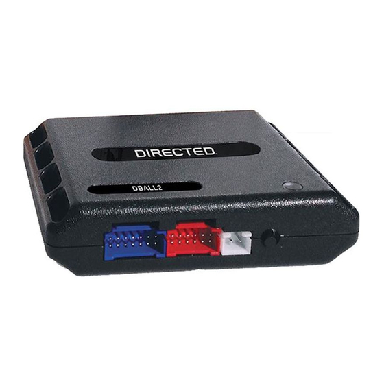
Platform: DBALL/DBALL2
Firmware: FORD5 Range Extender Ready (RXT) Installation
LED Diagnostics & Troubleshooting
LED
Description
Programming the Module
Off
Module has no power.
Waiting to begin the
Solid red
programming sequence.
CAN was detected.
Flashes green
Bypass is waiting for the
Solid orange
ignition startup.
Bypass was skipped.
Flashes orange
Module was successfully
Solid green
x 3 secs
programmed.
Module was successfully
Solid orange
x 3 secs
programmed without bypass.
Module Programming - Error Codes
Flashes red
CAN2 was not detected.
x 2
Flashes red
Bypass data was not detected.
x 3
Flashes red
Bypass processing error.
x 4
External Module Synchronisation
Flashes red,
OBDII feature is not supported.
red, then
orange x 10
Active Ground While Running
GROUND OUT ON (GWR)
Flashes green
command received.
D2D and W2W Commands
Flashes orange
Lock command received.
x 1
Flashes orange
Unlock command received.
x 2
Trunk release command
Flashes orange
x 3
received.
Troubleshooting
Make sure that 14-pin (blue) plug is connected and that 12 Volt is
present between the red and black wires. If the 12 Volt connection is
present, the module may be defective.
Make sure that all the connections are correct. See wiring diagram.
Normal operation.
Normal operation.
Normal operation. Immobilizer bypass programming was skipped.
Normal operation.
Normal operation. Immobilizer bypass programming was skipped.
Check the Tan - Tan/Black wire connections. Wake up the data bus
by turning the ignition on and try again.
Check the bypass line connection. If more than one wire is used,
make sure they are not inverted. Start vehicle using the key to
confirm the OEM equipment is still operational.
Bypass calculation failed. Reset the module and try again.
Diagnostic data bus was not detected. Some features are not
supported by SmartStart. This can be caused by missing wire
connections or module hardware limitation. Refer to "Installation
(wiring diagrams & vehicle wiring reference charts)" to check the
connections.
Otherwise, the Ground While Running (status) signal was lost or was
never received by the module.
If the bypass module fails to flash, it means the module did not
receive the signal. Verify the connections between the bypass and
the remote starter module.
Go to the next page to see the rest of the LED Diagnostics & Troubleshooting.
Rev.: 20160317
Page 9
© 2016 Directed. All rights reserved.
