SER 8540-B
Pump Tube (Inner Components)
23 Remove Pin (16) that secures Coupling (15) to the air motor rod.
• Unscrew the Coupling assembly from the air motor rod.
24 Clamp Coupling (19) in a soft-jaw vise.
25 Remove upper Pin (17) that secures Coupling (15) to Rod (18).
• Unscrew the Rod from the Coupling.
26 Remove lower Pin (17) that secures Coupling (19) to the Rod.
• Unscrew the Rod from the Coupling.
27 Remove Pin (38) that secures Piston (25) to Rod (37).
• Unscrew the Rod from the Piston.
28 Straighten the tabs on Locking Washer (24).
29 Unscrew Piston (25) from the Coupling.
30 Remove the Locking Washer from the Piston.
31 Remove Ball (23) from the Piston.
32 Remove Spring (22) and Washer (21) from Ball Stop (20).
NOTE: Separate the Ball Stop from the Coupling only if the
connection is loose.
33 Unscrew the Ball Stop from the Coupling as needed.
Pressurtrol
34 Remove Air Coupler (8) from Air Connector (7).
35 Loosen both Fittings (9) that secure Tube (11).
36 Loosen Pressurtrol (5) from Adapter (4).
• Remove the Tube from the Fittings.
37 Unscrew the Pressurtrol from the Adapter.
• Remove the Adapter from Air Motor (3) as needed.
38 Unscrew the Fitting from the Pressurtrol as needed.
39 Unscrew Angle Body (6) from the Pressurtrol as needed.
40 Unscrew Air Connector (7) from the Angle Body as needed.
41 Unscrew the additional Fitting from Adapter (10) as needed.
42 Remove the Adapter from the Air Motor as needed.
Clean and Inspect
NOTE: Use the appropriate repair kit for replacement parts.
Make sure all the components are included in the kit and in good
condition before discarding used parts.
1 Clean all metal parts in cleaning solvent. The solvent should be
environmentally safe.
2 Inspect all parts for wear and/or damage.
• Replace as necessary.
3 Inspect Piston (25) closely. Use a magnifying glass to detect any
wire draw marks.
• Replace as necessary.
4 Closely inspect the mating surfaces of all components for any im-
perfections. Ensure a smooth and clean contact is obtained when
assembled.
EXAMPLE: Place Ball (23) into Piston (25). Fill the Piston with
solvent. Make sure no leakage occurs.
Assembly
NOTE: Prior to assembly, certain components require lubrication
in clean oil. Refer to Table 4 for details.
Pump Tube (Inner Components)
NOTE: Refer to Figure 5 for a section view of the pum p tube
assembly.
1 Place Ball (23) into Piston (25).
2 Screw and seat Ball Stop (20) [ Loctite®242®]. into Coupling (19).
• Follow the thread sealant manufacturer's recommendations.
• Tighten securely.
3 Install Washer (21) and Spring (22) onto the Ball Stop.
Item No. on
Figure 2
12
O-Ring, 1-1/8" TD x 1-1/4" OD
29
Seal, 0.540" TD x 0.914" OD
34
Seal, 0.282" TD x 0.532" OD
42
O-Ring, 1" TD x 1-1/4" OD
4 Position Locking Washer (24) into the groove on the top of the
Piston.
5 Screw the Coupling assembly into the Piston.
• Tighten from 19 to 21 foot pounds (25.4 - 28.3 Nm)
• Continue to tighten and align the nearest flat of the Coupling
with the tabs on the Locking Washer.
IMPORTANT: Press on the Ball to ensure it moves a minimum of
1/8"
(3.2 mm) prior to contact with the Ball Stop. Should the value
be less, check to ensure the Ball Stop is fully seated in the Coupling.
6 Bend the tabs of the Locking Washer upward onto the Coupling.
7 Screw Rod (37) into the Piston until the pin holes align.
NOTE: Use a spot of grease on all pins to
movement.
Install Pin (38).
8
8
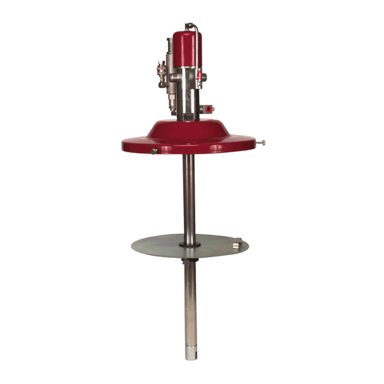
High Pressure Lubricant Pump
Description
prevent