- ページ 4
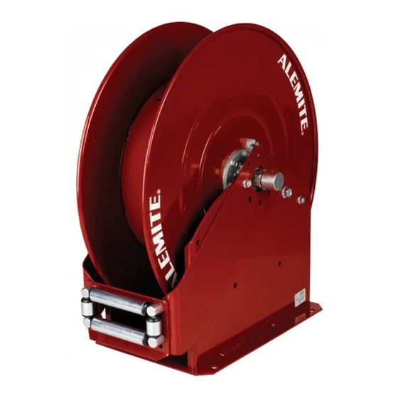
ツール Alemite 7344のPDF サービスマニュアルをオンラインで閲覧またはダウンロードできます。Alemite 7344 8 ページ。 High capacity twin hose reel

SER 7343
WARNING
Release all pressure within the system prior to
performing any maintenance procedure.
Turn off the power supply.
Operate the hydraulic tool to relieve the remaining pres-
sure within the system.
Maintenance
Read each step of the instructions carefully. Make sure a
proper understanding is achieved before proceeding.
Delivery Hose Replacement
1. Extend the delivery hose completely from the reel.
WARNING
Precautions must be taken to ensure the
Sheave Assembly remains engaged with the Power
Spring's ratchet. To prevent movement either:
• instruct an assistant to grip the Sheave Assembly
securely with non-slip gloved hands or
• install a clamp on the Sheave Assembly
Personal injury can occur.
2. Remove the hydraulic tool and hose stop.
3. Disconnect the delivery hose from 90 ° Unions (22).
4. Remove Wing Nuts (16) and Washers (15) that secure
U-Bolts (14) to the hose.
• Remove the hose.
5. Feed the end of the new delivery hose through the Hose
Guide Assembly.
6. Connect the delivery hose to the 90 ° Unions.
HINT: Orient the hose to allow its natural curve
to match the Sheave. This reduces torque load on
Power Spring Assembly (26).
7. Secure the delivery hose to the Sheave Assembly with
U-Bolts (14), Washers (15) and Wing Nuts (16).
8. Install the hydraulic tool (with thread sealant) and hose stop
to the delivery hose.
IMPORTANT: Allow some slack on the hose
between the U-Bolt and the 90 ° Unions.
9. Pressurize the system and check for leaks.
10. Carefully release the Sheave Assembly and retract the hose
onto the reel.
11. Check the Spring Tension.
• Please refer to the section entitled Installation for details.
Revision (11-08)
1-800-548-1191-http://[email protected]
Disassembly
WARNING
Release the tension on the power spring. Per-
sonal injury can occur.
Power Spring, Arbor, and Sheave Removal
1. Remove the Arm and Hose Guide assembly from Base
Assembly (8).
2. Unscrew Swivel Stem (2e) from Shaft and Flange Assembly
(20).
3. Disassemble the Swivel Assembly as required.
• See Figure 3.
4. Remove Screws (12) that secure Power Spring Assembly (26)
to the Base Assembly.
• Remove the Power Spring Assembly.
5. Remove Retaining Ring (5) that secures Spring Arbor (27) to
the Shaft and Flange Assembly.
• Remove the Spring Arbor and Key (21).
6. Remove Nuts (3) that secure the Bearing and Housing
assembly to the Base Assembly.
Item #
Part No.
2a
Ring, Retaining
2b
Ring, Back-Up
2c
X171009-17
O-Ring, 13/16 " ID x 1 " OD
2d
Body, Swivel
2e
340304
Stem, Swivel
2f
X171009-18
O-Ring, 7/8 " ID x 1-1/16 " OD
Legend:
Part numbers left blank are not available separately
Part number with an X prefix indicates a quantity of ten (10)
designates the parts available in Repair Kit 393781
Figure 3
Swivel Assembly 340305 - Exploded View
4
High Capacity Twin Hose Reel
Description
Notes Qty
Alemite, LLC
1
2
2
1
1
1
