- ページ 4
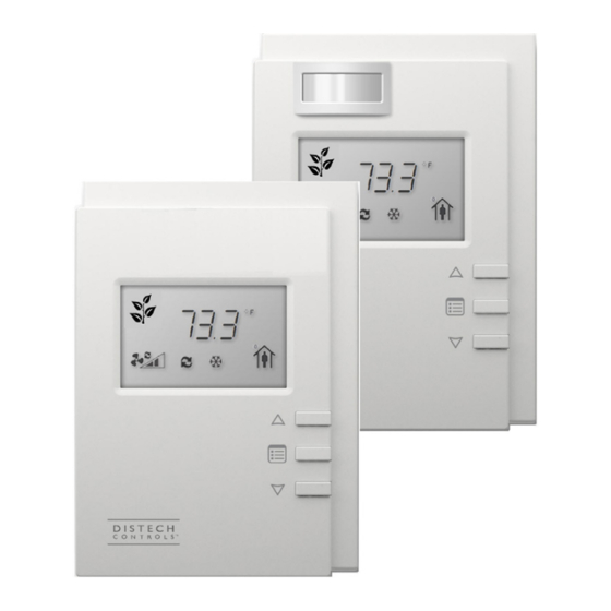
アクセサリー Distech Controls Allure ECL-600 SeriesのPDF インストレーション・マニュアルをオンラインで閲覧またはダウンロードできます。Distech Controls Allure ECL-600 Series 17 ページ。 Extension modules
Distech Controls Allure ECL-600 Series にも: インストレーション・マニュアル (16 ページ)
Mounting Instructions
The controller can be mounted on a DIN rail to speed up the installation procedure. They are also equipped with two mounting holes 0.25" x
0.165" (6.35mm x 4.191mm). The I/O Extension module can be mounted in a panel or on a wall by using appropriate screw types (use sheet metal,
thread forming, or self-tapping screws accordingly).
The controller's mounting orientation must be horizontal with controller's back attached to a vertical wall surface.
DIN Rail-Mounted Installation
1. Ensure the DIN rail is properly mounted on the wall.
2. Simply clip controller onto the DIN rail.
Wall-Mounted Installation
3. Open the enclosure by separating the front and back plate while pressing on the side clips.
4. Use the back plate's mounting holes to mark the location of any holes that need to be drilled.
5. Drill the holes.
6. Clean the surface and mount the controller using the appropriate screw types.
4 / 16
Figure 4:
Permitted Mounting Positions