- ページ 6
GPS Fleet Management MLT-400iのPDF インストレーション・マニュアルをオンラインで閲覧またはダウンロードできます。Fleet Management MLT-400i 14 ページ。
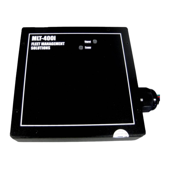
MLT-400i Installation Guide
3
Connect Power, Ignition and I/O
Two versions of the MLT-400i are available (check the product label located on the back of
the unit to determine which one you have): 1) the MLT-400iO is OBDII compatible; 2) the
standard MLT-400i uses a three-wire connection. Both are described below.
MLT-400iO OBDII Connection
• Ensure your vehicle is OBDII com-
patible, read the FMS OBDII "How
to Determine Compatibility"
available for download on Fleet
Central from
Admin|Support|UserGuides
• Connect the right angle OBDII
connector in to the vehicle OBDII
connector
MLT-400i Three-Wire Connection
The MLT-400i is shipped with one in-line 2-amp fuse attached to the power cable. This fuse
should be installed as close as possible to the primary 12 or 24 volt source connection. If the
power connection is more that 1-2 feet from the fuse an additional fuse must be added as
close to the power connection as possible should a short occur in the wiring. If a fuse is
added or replaced, it should be of the same type as originally supplied from the factory. The
original fuses supplied is one (2 Amp ATC BUSS fuse).
Use care when routing the power cable. Route the cables where they will be protected and
use commonly accepted install practices for aftermarket automotive electronic devices.
Using The MLT-400iO in Three-Wire Mode
•
Disconnect the OBD-II connector and attach ignition and power wires, (see MLT-400i
Three-Wire Connection above for more details)
•
Contact FMS Technical Support to issue the Reset Configuration Command
•
If you are using a Message Display Terminal (MDT-PRO), you must also connect both
the modem AND the MDT (using the white two pin connector) to the same power source
in addition to performing the steps above.
• Solder your connections (see Poke and Wrap below)
11/18/2009
FMS MLT-400i Installation Guide 4.3
Connect Power, Ignition and I/O
• The OBDII connector may be
located behind a panel, check your
vehicle documentation for the
location
• After installation validation, tie wrap
the connectors together, if possible,
and add a dot of inspection/torque
seal to detect tampering
• If your vehicle is not OBDII com-
patible, you can still use the modem
with the Three-Wire Connection
below. See inset below on Using the
MLT-400iO in Three-Wire Mode.
6